car logo Ford
car logo Volkswagen
car logo BMW
car logo Opel
car logo Audi
car logo Toyota
car logo Peugeot
English Русский
Български
Беларускі
Український
Српски
Hrvatski
Română
Polski
Slovenský
Magyar


Main
Freelander
Discovery
Range Rover
Defender
Contacts
Articles

Fuel injection pump and injection advance angle (Discovery 1)

 
  • Main
  • Discovery
  • Discovery 1
  • Power unit
  • Fuel system Tdi
  • Fuel injection pump and injection advance angle
 
        0  
Contents: Mounting pins ⇩ Removal ⇩ Installation ⇩
Note: The following text applies to vehicles with a manual transmission and without an electronic fuel injection pump control system. References to special tool replacement and additional information are provided for models with electronic control.


Mounting pins


Manual transmission, fuel injection pump without electronic control: LRT-12-044, installed in the flywheel housing base.

Manual transmission, electronically controlled fuel injection pump: LRT-12-O85, installed in the flywheel housing base.

Automatic transmission: LRT-12-044, installed in a large hole in the engine cover next to the oil pan. The finger must enter the toothed ring of the automatic transmission drive clutch.
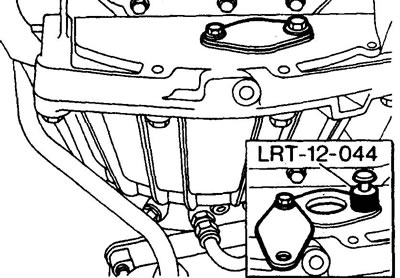
Automatic transmission: LRT-12-044, installed in a large hole in the engine cover next to the oil…


Removal


1. Disconnect the battery.

2. Remove the high pressure pipes from the fuel injection pump.

3. Remove the oil filler cap.

4. Bring the piston of the 1st cylinder to TDC of the compression stroke. Make sure the correct TDC is set using the cams visible through the oil filler neck.

5. Replace the oil filler cap.

6. Remove the plug from the flywheel housing base.


7. Install the LRT-12-044 pin onto the crankcase, do not engage the center pin of the pin.
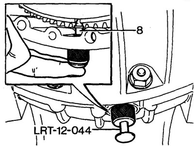
7. Install the LRT-12-044 pin onto the crankcase, do not engage the center pin of the pin.


8. While slightly rocking the crankshaft, insert the pin into the flywheel slot.

9. Remove the fuel injection pump drive cover from the front engine cover.

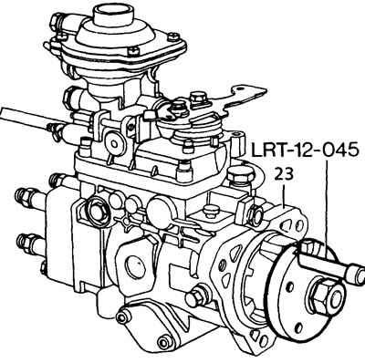
10. Insert the LRT-12-045 mounting pin into the fuel injection pump drive gear.
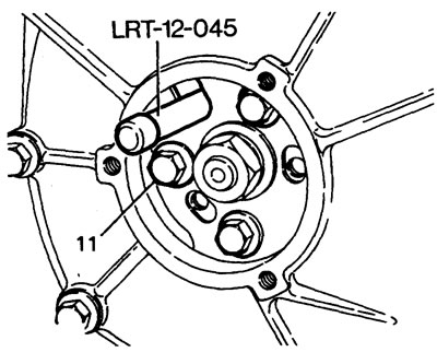
10. Insert the LRT-12-045 mounting pin into the fuel injection pump drive gear.


11. Loosen the bolts securing the gear to the pump hub. Do not unscrew the central hub nut.

12. Remove the mounting pin.

13. Install the LRT-12-045 gear lock and secure it with bolts, placing additional 2 mm washers under the bolt heads.
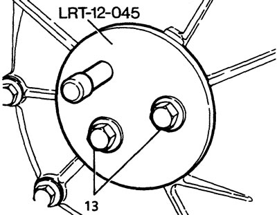
13. Install the LRT-12-045 gear lock and secure it with bolts, placing additional 2 mm washers…


14. Disconnect the fuel injection pump lever cable. If equipped, disconnect the manual drive cable.


15. Disconnect the wire from the fuel shut-off valve.

16. Disconnect the fuel supply and outlet pipes, and the boost corrector pipe. Screw the tube mounting bolts back into place on the fuel injection pump.
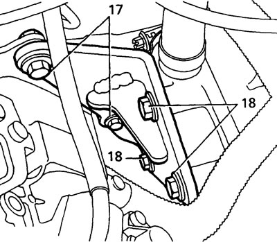
16. Disconnect the fuel supply and outlet pipes, and the boost corrector pipe. Screw the tube…


17. Unscrew the two bolts of the rear support of the fuel injection pump.

18. Loosen the bolt securing the rear support bracket to the block so that the bracket can move.

19. Unscrew the fuel injection pump flange mounting nuts, remove the fuel injection pump and gasket.

20. Plug the fuel lines and fuel injection pump fittings.

Installation


21. Remove the plugs from the fittings.
21. Remove the plugs from the fittings.


22. Install the LRT-12-045 pin into the hub and the fuel injection pump housing.

23. Clean the mating surfaces of the fuel injection pump flange and the front engine cover.


24. Install the fuel injection pump with a new gasket, tighten the mounting nuts to a torque of 25 N·m.

25. Tighten the rear fuel pump support fasteners by hand.

26. Tighten the rear support bracket bolt to the block, then tighten the rear support bolts.

27. Connect the fuel lines, tighten the bolts to a torque of 25 N·m.

28. Connect the boost control tube and tighten the bolt to 10 Nm.

29. Connect the fuel shut-off valve wire.

30. Connect the fuel injection pump lever cables.

31. Remove pin LRT-12-045.

32. Install the drive gear retaining plate.

33. Install the LRT-12-045 pin.

34. Secure the gear to the fuel injection pump hub with three bolts.

35. Remove pin LRT-12-045.

36. Release the flywheel lock, turn the engine two revolutions, install the flywheel lock. Check the possibility of free installation of the pin into the fuel injection pump hub.

37. If the pin cannot be installed in the fuel injection pump, then:
  • a) disengage the flywheel mounting pin
  • b) turn the crankshaft until the pin is installed in the fuel injection pump hub
  • c) loosen the fuel injection pump drive gear mounting bolts
  • d) turn the crankshaft to TDC
  • d) secure the flywheel with the installation pin; e) tighten the fuel injection pump drive gear mounting bolts
  • g) remove the mounting pins.

38. Apply anti-seize compound to the threads of the flywheel housing base plug bolts and tighten the bolts to a torque of 12 Nm.

39. Install the fuel injection pump drive cover and tighten the bolts to a torque of 25 Nm.

40. Install the high pressure pipes, tighten the pipe nuts to a torque of 28 N·m.


This article is available at russian, bulgarian, belarusian, ukrainian, serbian, croatian, romanian, polish, slovak, hungarian
Article review: Konstantin Nazarov


Previous articles
Tdi fuel system — design description
Description of the electronic fuel injection pump control system
Operation of the electronic control system
Adjustments — accelerator cable (fuel injection pump lever)
Fuel injection pump lever position sensor (for the exhaust gas recirculation system)
Idle speed
Checking the boost pressure
Repair — Fuel Level Sensor

Current article
Fuel injection pump and injection advance angle

Next articles
Engine control unit
Air flow sensor
Boost pressure sensor
Injector needle lift sensor
Speed sensor
Vehicle speed sensor
Clutch pedal switch
Brake pedal switch


Similar articles from Land Rover repair manuals:
• Fuel pump and fuel supply unit Freelander 2 (2006-2014)
• High pressure fuel pump and fuel filter assembly Freelander 1 (1997-2006)
• Secondary Air Injection (SAI) Pump Relay Range Rover 3 (2001-2012)
• Cleaning of fuel injection system components Defender 2007+ (2007-2016)

Comments on this article


No comments yet


How much will 30 + 47 =


Discovery 3 
  • General information
  • Using the manual
  • Precautionary measures
  • Service Information
  • Technique
  • Health protection
  • Road test
  • Identification codes
  • Jacking and lifting
  • Maintenance - diesel
  • Maintenance - petrol
  • Chassis
  • Suspension
  • Front suspension
  • Rear suspension
  • Wheels and tires
  • Dynamic suspension
  • Cardan shaft
  • Rear drive axle
  • Front drive axle
  • Front axle axles
  • Rear axle axles
  • Brake system
  • Parking brake
  • Hydraulic brake
  • Vacuum brake booster
  • Anti-lock braking system
  • Steering
  • Steering column
  • Power unit
  • Petrol engine 4.0L
  • Petrol engine 4.4L
  • Diesel engine 2.7L
  • Engine cooling
  • Fuel supply
  • Drive units
  • Launch system
  • Ignition system
  • Emission reduction
  • Air filtration
  • Fuel vapor control
  • Electronic control part
  • Car gearbox
  • Clutch
  • All-wheel drive systems
  • Transfer case
  • Exhaust system
  • Fuel tank and lines
  • Acceleration control
  • Electrical equipment
  • Climate control
  • Instruments and control lamps
  • Battery and charging system
  • Information system
  • Lighting and headlights
  • Power distribution
  • Electronic Function Group
  • Body and coating
  • Body elements
  • Interior and body trim
  • Mirrors and glasses
  • Seats
  • Instrument panel and console
  • Handles and locks
  • Windshield wipers and washers
  • Sunroof and bumpers
  • Safety system
  • Body repairs
  • Repair of front end elements
  • Repair of back elements
  • Side panel repair
  • Frame and body mount

Discovery 1 
  • General information
  • Technical specifications
  • Introduction to manual
  • Troubleshooting
  • Power unit
  • Diesel engine Tdi
  • Petrol engine V8i (3.9 l)
  • Petrol engine V8i (4.0 l)
  • Petrol engine Mpi
  • Reducing harmful emissions
  • Fuel system Tdi
  • Fuel system MFi
  • Fuel system SFi
  • Fuel system MPi (MEMS)
  • Cruise control
  • Cooling system (Tdi)
  • Cooling system (V8i)
  • Cooling system (MPi)
  • Exhaust system
  • Transmission
  • Clutch
  • Manual gearbox R380
  • Manual gearbox LT 77
  • Transfer case LT230T
  • Automatic gearbox
  • Cardan shaft
  • Rear axle
  • Front axle
  • Chassis
  • Steering system
  • Front suspension
  • Rear suspension
  • Brake system
  • Wheels and tires
  • Body and interior
  • Passive safety
  • Doors, locks and windows
  • Exterior body parts
  • Interior trim details
  • Seats
  • Electrical equipment
  • Heating and ventilation
  • Air conditioning
  • Windscreen wipers
  • Starting and charging system
  • Equipment and devices
  • Lighting and headlights


LRman.ru © 2013-2026 | Mobile version | Free Lander | Discovery | Range Rover | Defender | Contacts | | Sitemap |
Car repair and service instructions Land Rover: Freelander, Discovery, Range Rover, Defender
We use cookies to make pages load faster and provide a more user-friendly experience 🍪