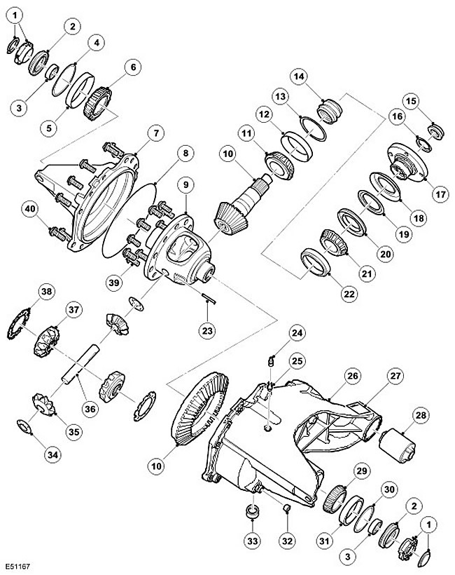
| Item name | Spare part catalog number | Description |
| 1 | - | Lid |
| 2 | - | Sealing |
| 3 | - | Bearing assembly without cage |
| 4 | - | Bearing preload spacer sleeve |
| 5 | - | Bearing |
| 6 | - | Outer ring of roller bearing |
| 7 | - | Lid |
| 8 | - | Sealing |
| 9 | - | Differential cup |
| 10 | - | Gear assembly |
| 11 | - | Bearing |
| 12 | - | Outer ring of roller bearing |
| 13 | - | Washer |
| 14 | - | Deformable spacer sleeve |
| 15 | - | Pinion Nut |
| 16 | - | Clamp |
| 17 | - | Flange |
| 18 | - | External deflector |
| 19 | - | Internal deflector |
| 20 | - | Oil seal |
| 21 | - | Bearing |
| 22 | - | Outer ring of roller bearing |
| 23 | - | Cylindrical pin |
| 24 | - | Breather cap |
| 25 | - | Breather |
| 26 | - | Frame |
| 27 | - | Data location |
| 28 | - | Mounting sleeve |
| 29 | - | Bearing |
| 30 | - | Bearing preload spacer sleeve |
| 31 | - | Outer ring of roller bearing |
| 32 | - | Plug |
| 33 | - | Drain plug |
| 34 | - | Thrust washer |
| 35 | - | Planetary gear |
| 36 | - | Cross shaft |
| 37 | - | Sun wheel |
| 38 | - | Thrust washer |
| 39 | - | Bolt, 10 pcs. |
| 40 | Bolt, 12 pcs. |
The cast iron body consists of two parts: a cup and a cover. The cup contains all the internal parts. The cup is attached to the cover with 12 bolts, and the joint is sealed with a ring seal. The cover and cup have cast ribs for increased mobility. A breather tube is fixed to the top of the cup. This allows you to install a plastic tube and bring it out at a high point under the car body to prevent water from entering when the car is fording.
The cup has a drain plug for oil. The differential capacity is approximately 1.6 liters when dry. At subsequent replacement, less oil will be required due to the non-drainable residue in the gear housing.
The differential is of a traditional hypoid gear design similar to that used in the front differential. There are 3 types of open rear differentials with different gear ratios. V8 petrol engine vehicles use a differential with a final drive ratio of 3.73:1, while V6 petrol engine vehicles use a differential with a final drive ratio of 3.73:1. TdV6 vehicles with an automatic transmission have a final drive ratio of 3.54, while those with a manual transmission have a final drive ratio of 3.07. Changing the number of teeth between the driven gear and the driving gear of the final drive changes the gear ratio.
The differential consists of a pinion shaft, a hypoid gear, and a driven gear of the main transmission with an integrated housing containing 2 planetary gears. The housing also contains 2 sun gears that transmit torque to the drive shafts.
The pinion shaft is mounted on two opposing tapered roller bearings with a deformable bushing between them. The bushing is used to center the bearings and is also deformed when force is applied to the flanged pinion nut. This allows the flanged nut to be tightened to a specified torque, at which the bushing is deformed, providing the necessary bearing preload.
The pinion shaft has a splined outer end that engages with the primary flange, which is secured with a pinion nut and clamp. The primary flange has 4 threaded holes and connects to the rear drive shaft. 4 bolts secure the rear drive shaft to the primary flange. A seal is pressed into the gear housing, which seals the connection between the primary flange and the gear housing. A hypoid gear is installed on the inner end of the pinion shaft, engaging with the driven gear of the main transmission.
The driven gear is located on the differential housing and is secured with 10 screws. The differential housing is mounted on tapered roller bearings placed in machined holes on both sides of the gear train. Washers are retained in the housing behind the bearing caps.; their thickness is selected in such a way as to ensure the required bearing preload and hypoid gear clearance.
The differential cup has a through hole for the shaft. The shaft is supported by a sun gear and a needle roller bearing. At one end of the shaft there is a retaining ring that fits into a machined groove in the sun gear, fixing the position of the shaft.
(Information obtained from the website: LRman.ru)
The sun gears are located in recesses in the cup body and engage with the planet gears. Spacers are installed between the sun gears and the cup to ensure proper engagement of the sun and planet gears. Each sun gear has a machined bore with internal splines and a machined groove near the splined end. This groove provides a positive hold for the retaining ring mounted on the end of each output flange.
Each output shaft has a splined portion that engages with the sun gear. A retaining ring mounted on the splined shaft fits into a groove in the sun gear hole and firmly fixes the output shaft. Seals are pressed into each side of the gear housing to seal the output shaft.
Comments on this article