CAUTION: Make sure the vehicle is on a flat, level surface.
CAUTION: Make sure the tire pressure is correct.
CAUTION: Use only the equipment recommended by the manufacturer to adjust the four wheel alignment angles.
CAUTION: Make sure the vehicle's fuel tank is full. If it is not, evenly distribute ballast around the fuel tank to match a full fuel tank.
CAUTION: Make sure there are no heavy objects in the vehicle.
CAUTION: Make sure the air suspension height is set to NORMAL.
CAUTION: Make sure the steering wheel is straight ahead.
CAUTION: Before adjusting the geometry, make sure the turntables move freely.
NOTE: This procedure is for both air and coil spring suspension vehicles.
1. Check tie rod ends, suspension joints, hub bearings, wheel rims and tires for damage, wear and play.
- Adjust or repair worn, damaged or improperly adjusted parts.
2. Check and adjust tire pressure.
3. Place the vehicle on a calibrated horizontal vehicle lift.
4. Release the parking brake.
5. Vehicles with Dynamic Suspension: Using an approved scan tool, check the air suspension control module for DTCs and clear codes if necessary.
6. Vehicles with dynamic suspension: Using the scan tool, set the vehicle to 'Geometry Set Mode' using the instructions below. (geometry adjustment mode). Switching the car to this mode will allow you to more accurately control the ground clearance.
- Select the 'Configuration' tab (configuration).
- Select 'Set up and Configure' (set up and configure).
- Select 'Air Suspension' (air suspension).
- Select 'Suspension Geometry Set Up' (suspension geometry adjustment).
- Select 'Tight Tolerance Mode' (tight tolerance mode).
- Follow the on-screen instructions until the setup process is complete.
7.
NOTE: If rear camber adjustment is required, loosen the rear camber adjustment bolts enough to allow adjustment before making other wheel alignment adjustments. Do not loosen the rear camber adjustment bolts completely.
Check and adjust wheel alignment using only Land Rover recommended four-wheel alignment equipment.
8.
CAUTION: Before tightening the toe rod mounting nut, make sure the rod end is fully seated in the body frame. Failure to do so will result in damage to the toe rod or the body frame.
NOTE: This operation is only required if the toe-in rods have been removed or replaced.
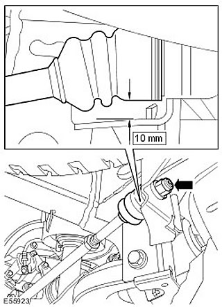
Adjust rear steer on bumps.
- Loosen the inner ball joint mounting nut of the toe adjustment rod.
- Set a gap of 10 mm between the underside of the rubber boot of the toe adjustment rod and the body frame bracket.
- Tighten the inner ball joint mounting nut of the toe adjustment rod (tightening torque 133 Nm).
- Repeat the above procedure on the other side.
9.
NOTE: The rear camber adjustment bolts cannot be tightened when the rear wheels are installed. Do not remove the rear wheels to tighten the rear camber adjustment bolts until other wheel alignment adjustments have been made.
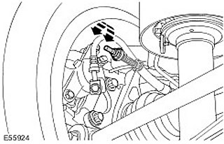
Adjust the rear wheel alignment.
- Loosen the rear wheel alignment bolts.
- Turn the rear camber adjustment bolt until the desired value is obtained.
- Repeat the above procedure on the other side.
- Tighten the rear wheel alignment bolts.
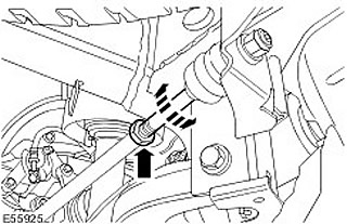
10. Adjust the rear wheel alignment.
- Loosen the toe adjustment rod lock nut.
- Turn the inner ball joint of the toe adjustment rod until the desired rear wheel toe-in value is obtained.
- Tighten the toe adjustment rod lock nut. (tightening torque 130 Nm).
- Repeat the above procedure on the other side.
- Measure the rear wheel alignment.
11.
CAUTION: Before adjusting the geometry, make sure the turntables move freely.
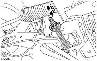
Adjust the front wheel alignment.
- Loosen the front lower arm camber adjustment bolt.
- Turn the front lower arm camber adjustment bolt until the desired value is obtained.
- Tighten the lower arm front camber adjustment bolt (tightening torque 275 Nm).
- Repeat the above procedure on the other side.
12. Adjust the longitudinal angle of the front wheel steering axis.
- Loosen the rear lower arm pivot axis caster angle adjustment bolt.
- Turn the caster angle adjustment bolt until the desired value is obtained.
- Tighten the rear lower arm castor angle adjustment bolt.
- Repeat the above procedure on the other side.
- Measure the caster angle again.
- Repeat the above procedure until the correct caster angle value for both wheels is obtained.
- Tighten the rear lower arm castor adjustment bolts. (tightening torque 275 Nm).
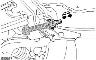
13. Set the steering wheel to the straight-ahead position.
- Measure the length of the visible threaded portion of each rod.
- If the visible threaded part differs by more than 2 mm:
- Step 1: Loosen the lock nut on one tie rod end.
- Step 2: Turn the tie rod until the visible threaded portion of both tie rods is the same.
- Step 3: Tighten the tie rod end lock nut.
- Stage 4: Turn the steering wheel until the toe-in of both front wheels is equal.
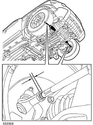
14. If the steering wheel deviates more than three degrees from the straight-ahead position, remove the steering wheel and reinstall it, moving it one spline in the straight-ahead direction. Steering Wheel (57.61.01)
- Set the steering wheel to the straight-ahead position.
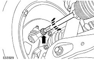
15. Adjust the front wheel alignment.
- Loosen the tie rod end locknuts.
- Set the required toe-in value for each front wheel by turning the rods.
- Tighten the tie rod end locknuts (tightening torque 53 Nm).
16. Vehicles with dynamic suspension: Using the scan tool, return the vehicle to 'Normal Mode' (normal mode).
- Select the 'Configuration' tab (configuration).
- Select 'Set up and Configure' (set up and configure).
- Select 'Air Suspension' (air suspension).
- Select 'Suspension Geometry Set Up' (suspension geometry adjustment).
- Select 'Normal Mode' (normal mode).
- Follow the on-screen instructions until the process is completed for normal mode.
17.
CAUTION: Do not work on or under a vehicle that is supported only by a jack. Always support the vehicle securely.
Raise and support the vehicle.
18. Remove the rear wheels with tires.
19. Tighten the rear wheel alignment bolts. (tightening torque 113 Nm).
20. Install the wheels and tires.
- Tighten the wheel nuts to a torque of 140 Nm.
21. Using the scan tool, calibrate the steering wheel angle sensor.
Comments on this article