The ignition distributor is driven by the camshaft gear.
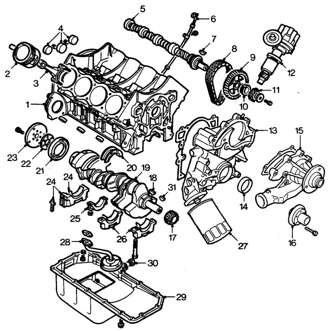
1 - cylinder block, 2 - piston and piston pin, 3 - connecting rod, 4 - plugs, 5 - camshaft, 6 - oil dipstick, 7 - key, 8 - timing chain, 9 - camshaft sprocket, 10 - spacer, 11 - distributor drive gear, 12 - distributor, 13 - front cover, 14 - front oil seal, 15 - water pump, 16 - crankshaft damper pulley, 17 - crankshaft sprocket, 18 - key, 19 - crankshaft, 20 - thrust bearing half rings, 21 - rear oil seal, 22 - spacer, 23 - adapter, 24 - cover, liner and seals of the rear main bearing, 25 - connecting rod cover, 26 - cover and liner main bearing, 27 - oil filter, 28 - oil intake, 29 - pan, 30 - drain plug, 31 - key
Lubrication system
The V8i engine's full-flow lubrication system features a crankshaft-driven gear oil pump. The pump body is the front cover of the engine. The pressure relief valve, oil pressure sensor and oil filter are also installed there.
Oil from the sump is sucked in by the pump through a mesh intake and supplied under pressure to the oil cooler built into the radiator of the cooling system. From the cooler, the oil flows into the filter and then into the engine's main oil line.
[Details can be found on the website: www.lrman.ru]
The cylinder liner walls are lubricated through holes in the connecting rods.
Lubrication of the chain and distributor drive
Oil is supplied to the chain and drive from the first main bearing of the crankshaft.
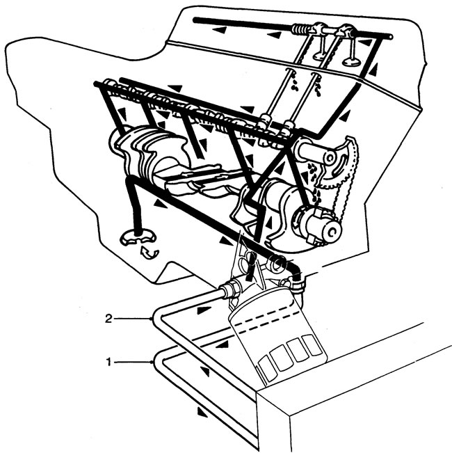
1 - to the cooler, 2 - from the cooler.
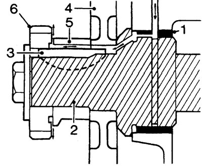
1 - bearing, 2 - crankshaft, 3 - key, 4 - sprocket, 5 - spacer, 6 - distributor drive gear.
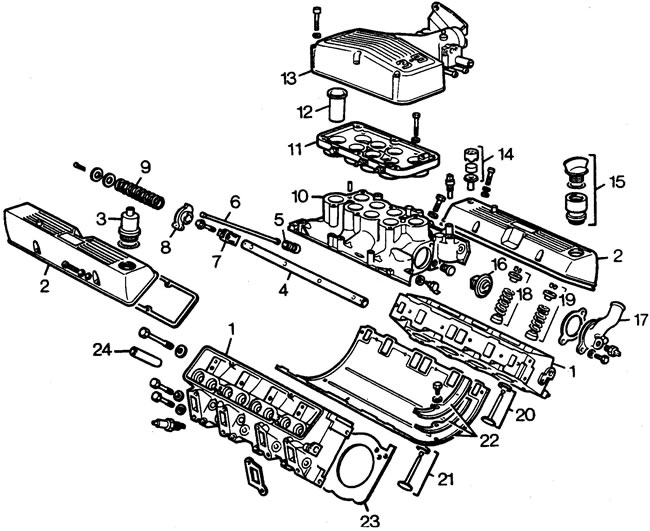
1 - cylinder head, 2 - valve cover, 3 - crankcase ventilation valve filter, 4 - rocker arm shaft, 5 - hydraulic tappet, 6 - tappet rod, 7 - rocker arm shaft support, 8 - inlet rocker arms (4 pcs.) and outlet rocker arms (4 pcs.), 9 - rocker arm shaft springs (6 pcs.), 10 - intake manifold, 11 - lower part of the resonance chamber (venturi nozzle housing), 12 - Venturi nozzles (8 pcs.), 13 - upper part of the resonance chamber, 14 - crankcase ventilation valve air filter, 15 - oil filler neck, 16 - thermostat, 17 - thermostat cover, 18 - spring seat, spring, valve plate and crackers (intake), 19 - spring seat, spring, valve plate and crackers (outlet), 20 - intake valve and seat, 21 - exhaust valve and seat, 22 - intake manifold gaskets, 23 - cylinder head gaskets, 24 - valve guides.
Hydraulic pusher
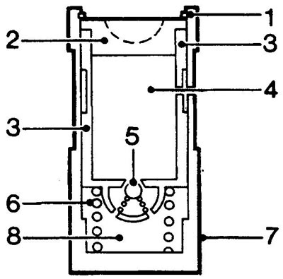
1 - retaining ring, 2 - rod seat, 3 - inner sleeve, 4 - upper chamber, 5 - check valve, 6 - spring, 7 - outer sleeve, 8 - lower chamber (high pressure).
Oil from the lubrication system enters the upper chamber (4), passes through the check valve (5), and into the lower chamber (8). When the cap begins to lift the pushrod (outer sleeve (7)), the resistance of the valve spring is transferred to the rod seat (2), moving the inner sleeve (3) downward. This movement closes the check valve (5), causing the pressure in chamber (8) to increase sufficiently to overcome the force of the valve spring and begin opening the valve.
When the engine valve reaches its maximum lift, the check valve (5) opens, equalizing the pressure in both chambers of the tappet, thereby ensuring that the valve seats on the seat at the end of the cam run.
Comments on this article