Contents: Removal and installation ⇩ Checking the constant velocity joint ⇩ Installing a constant velocity joint ⇩ Replacement of the drive shaft…⇩ Steering knuckle ⇩ Steering knuckle parts ⇩ Removal the bearing housing ⇩ Installing the bearing housing ⇩ Adjusting bearing preload ⇩
Removal and installation
1. Remove the front hub.
2. Drain the oil from the steering knuckle housing.
3. Unscrew the six bolts securing the drive shaft housing to the steering knuckle.
4. Remove the mudguard.
5. Remove the drive shaft housing and sealing washer.
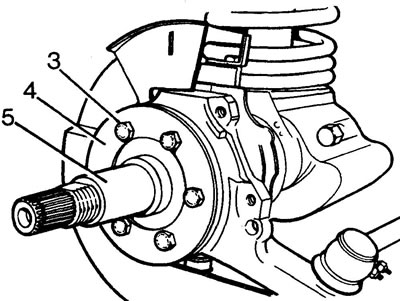
6. Remove the drive shaft, intermediate shaft and CV joint from the steering knuckle.
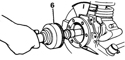
7. Clamp the drive shaft in a vice.
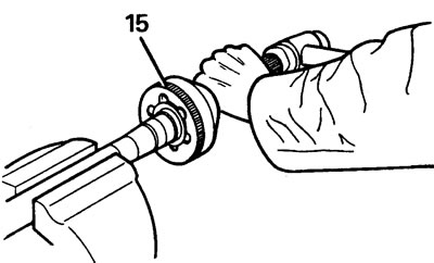
8. Using a plastic hammer, knock the CV joint off the intermediate shaft.
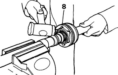
9. Remove the retaining ring and spacer.
Checking the constant velocity joint
10. Mark the relative positions of the outer and inner CV joint rings and separator for subsequent assembly.
11. Remove the balls by rotating and rocking the inner ring and separator.
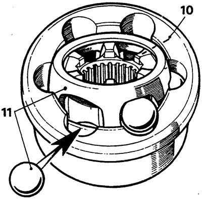
12. Check the condition of the CV joint parts.
13. Assemble the CV joint and check the axial clearance. If the axial clearance is more than 0.64 mm, replace the joint.
Installing a constant velocity joint
14. Install the new retaining ring and spacer.
15. Place the CV joint on the splines of the intermediate shaft and drive it in with a hammer with a plastic striker.
Replacement of the drive shaft housing, thrust ring, seal and bearing
16. Drill and chisel the thrust ring. Caution! Do not damage the drive shaft housing.
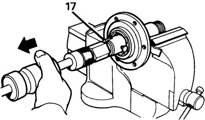
17. Remove the bearing and seal using the LRT-37-004 drift and the LRT-99-004 inertial puller. Make sure that the edge of the drift goes behind the bearing ring.
18. Remove the oil seal in the same way.
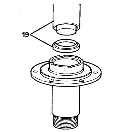
19. Lubricate the new oil seal with EP90 grease and install it in place using the LRT-54-004 mandrel.
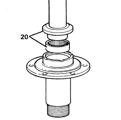
20. Using the LRT-54-005 mandrel, install the bearing flush with the housing.
21. Press on a new thrust ring.
Steering knuckle
22. Loosen the bolts securing the oil seal plate to the bearing housing, move the oil seal and plate away.
Attention: removal of the plate and oil seal is carried out after removing the steering knuckle bearing housing from the axle beam.
23. Unscrew the two bolts securing the lower pivot pin.
24. Remove the brake disc protection bracket.
25. Bend back the lower pivot pin retaining tab, remove the pin and washer.
26. Remove the two bolts securing the upper pivot pin and brake hose bracket.
27. Remove the bracket, pin and adjusting washers.
28. Remove the steering knuckle.
Steering knuckle parts
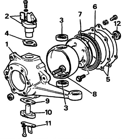
1 - steering knuckle, 2 - upper steering pin bracket, 3 - bearings, 4 - adjusting washer, 5 - oil seal plate, 6 - oil seal, 7 - gasket, 8 - bearing housing, 9 - gasket, 10 - lower steering pin, 11 - brake disc protection bracket, 12 - inner oil seal.
Removal the bearing housing
29. Knock out the lower bearing ring through the hole in the upper bearing.
The material was taken from a website (LRman.ru)
30. Unscrew the seven bolts securing the bearing housing to the axle beam.
31. Remove the inner oil seal.
32. Remove the upper bearing ring.
33. If the housing sphere is worn, replace the bearing housing.
34. Install new bearing rings into the housing. Caution: Bearing rings must be installed tightly.
35. Install the new inner oil seal and lubricate it with grease.
Installing the bearing housing
36. Apply Loctite 270 adhesive to the threads of the housing mounting bolts.
37. Apply sealant to both sides of the housing gasket, install the housing on the bridge beam.
38. Check the sequence of installation of the housing sphere seal and its retaining plate on the housing.
39. Tighten the housing mounting bolts to 73 Nm.
40. Pack the pivot pin bearings with grease.
41. Install the pin housings onto the bearings.
42. Apply sealant to both sides of the lower finger gasket and install it.
43. Install the brake disc protection bracket and the lower pin with the tab towards the outside of the bearing housing.
44. Install the upper pivot pin, adjusting washer and brake pipe bracket.
45. Apply Loctite 270 adhesive to the threads of the pin mounting bolts and tighten the lower pin mounting bolts to 78 Nm. Bend back the locking tabs.
46. Tighten the upper pin mounting bolts to 78 Nm.
Adjusting bearing preload
Note: When adjusting the preload, do not install the steering knuckle seals.
47. Using the steering knuckle lever and a dynamometer, turn the knuckle. The turning force should be 1.16-1.46 kgf. Preload can be adjusted by replacing the upper pivot pin adjusting washer.
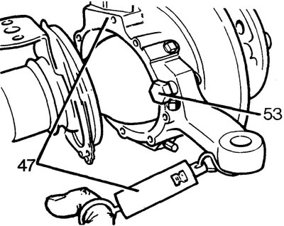
48. After adjustment, apply Loctite 270 adhesive to the pin mounting bolt threads and tighten the upper pin mounting bolts to 78 N·m.
49. Lubricate the sealing lips of the bearing housing oil seals.
50. Install the oil seal, gasket and retaining plate. Tighten the board mounting bolts to 11 Nm.
51. Install the transverse and longitudinal steering rods. Tighten the mounting nuts to a torque of 40 Nm and secure the nuts with a new cotter pin.
52. Install the brake disc guard.
53. Loosen the wheel stop nut and bolt.
54. Reinstall the removed parts. When assembling:
- apply Loctite 270 adhesive to the bolt threads.
- the drive shaft housing is installed by making a flat cut on the thread of the tip in the "12 o'clock" position.
- adjust the position of the wheel turning limiter (20 mm gap between the bolt head and the steering knuckle, see. "Steering").
- fill the steering knuckle with oil to the level of the filler plug.
Comments on this article