Special tool
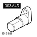 Valve timing tool 303-645 Valve timing tool 303-645 | 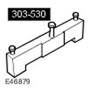 Camshaft Installation/Locking Tool 303-530 Camshaft Installation/Locking Tool 303-530 | 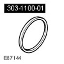 Adapter for crankshaft oil seal installation device 303-1100-01 Adapter for crankshaft oil seal installation device 303-1100-01 |
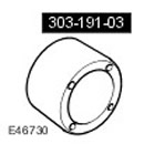 Adapter 303-191-03 Adapter 303-191-03 | 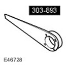 Crankshaft Pulley Locking Tool 303-893(LRT-12-080) Crankshaft Pulley Locking Tool 303-893(LRT-12-080) |  Bolts and spacers 303-191-04 Bolts and spacers 303-191-04 |
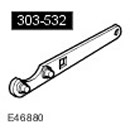 Timing Chain Tensioner Tool 303-532 Timing Chain Tensioner Tool 303-532 |
Assembly
1. Secure the engine to the engine stand.
- Adjust the engine position on the engine stand.
- Adjust the position of the engine stand legs.
- Place the engine on an engine stand.
- Fully tighten the engine stand leg nuts.
NOTE: Install a new gasket.
Install the oil pump assembly.
- Clean the mating surfaces of the elements.
- Install the gasket.
- Tighten the bolts to 10 Nm.
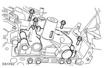
3. Install the reflector plate. Tighten the 6 bolts to 6 Nm.
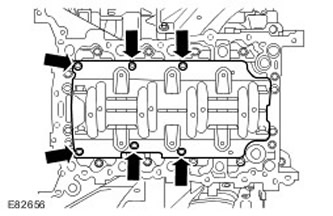
4.
NOTE: Install a new O-ring.
Install the oil intake pipe with the mesh filter assembly.
- Install the sealing ring.
- Tighten the M6 bolt to 10 Nm.
- Apply sealant to the M5 bolts.
- Tighten the M5 bolts to 6 Nm.
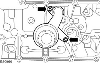
5. Install the oil pan.
- Clean the mating surfaces of the elements.
- Apply a 3mm bead of sealant to the area shown.
- Screw in the bolts, but do not tighten them completely yet.
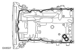
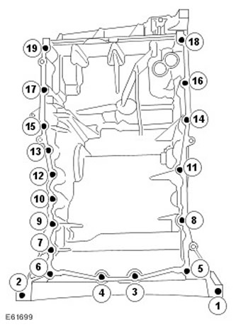
6. Tighten the oil pan bolts in the sequence shown to 20 Nm.
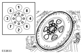
7.
NOTE: Stop the faceplate from rotating.
Install the faceplate.
- Clean the mating surfaces of the elements.
- Tighten the bolts evenly in 2 stages in the sequence shown.
- Tighten the bolts to 15 Nm.
- Tighten the bolts to 110 Nm.
8. Install the coolant pump. Tighten the 5 bolts to 10 Nm.
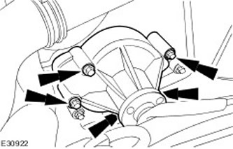
9.
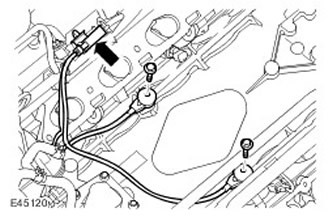
NOTE: There may be some differences from what is shown in the pictures, but the basic information is correct.
Install the knock sensors (KS). Tighten the bolts to 20 Nm.
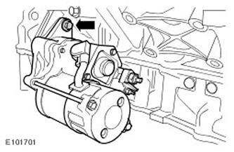
10. Install the starter. Install the starter. Tightening torque: 45 Nm.
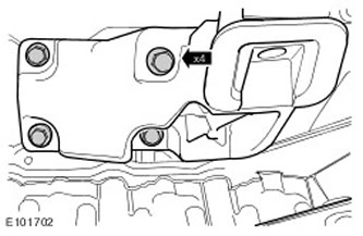
11. Attach the engine mount bracket.
12.
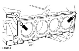
NOTE: Cylinder head gaskets must be installed on the cylinder block studs.
Install the right cylinder head.
- Clean the mating surfaces of the elements.
- Clean the cylinder head dowel pins.
- Install a new cylinder head gasket.
- Install the cylinder head with assistance.
- Repeat the operation on the left side.
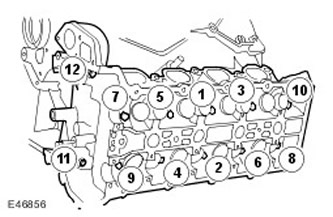
13.
NOTE: Tighten bolts 1 through 10 in the sequence shown.
NOTE: Left side shown, same for right side.
Screw in the cylinder head bolts.
- Tighten the bolts to 20 Nm.
- Tighten the bolts to 35 Nm.
- Tighten bolts 1 through 10 another 90 degrees.
- Tighten bolts 1 through 10 another 90 degrees.
- Tighten bolts M8 11 and 12 to 25 Nm.
- Repeat the operation on the left side.
14. Install the left camshafts.
- Clean the mating surfaces of the elements.
- Lubricate the camshaft journals and cams.
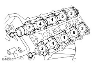
16. Install the Torx head bolts to secure the sprockets to the camshafts.
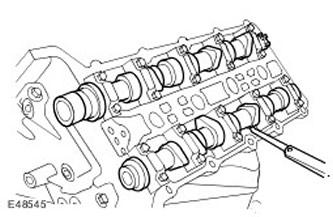
17.
CAUTION: The camshaft lobes must be rotated 180 degrees from the corresponding valve lifters, otherwise the valve clearance will be incorrect.
Measure and record valve clearances. Turn the camshafts using Torx bolts.
18.
NOTE: Loosen the camshaft bearing caps evenly and gradually.
NOTE: Remove the camshaft bearing caps. Note: Remember their position, direction and marking. Each cap is marked with its position (number) and direction (arrow).
Remove the camshafts. Remove 20 bolts.
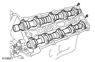
19. Remove the valve lifters and replace them with the selected lifters.
20. Install the camshafts.
- Lubricate the camshaft journals and cams.
- Clean the mating surfaces of the elements.
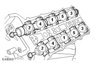
22.
CAUTION: The camshaft lobes must be rotated 180 degrees from the corresponding valve lifters, otherwise the valve clearance will be incorrect.
Check that the valve clearances are adjusted correctly.
- Turn the camshafts using the Torx bolts.
- Once the inspection is complete, remove the Torx head bolts from the camshafts.
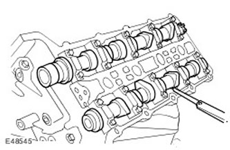
23. Repeat the operation for the right camshafts.
24. Install the special tool on the left cylinder head.
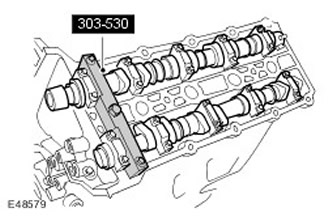
25.
NOTE: The picture shows the right side, the same for the left side.
Press the piston of the left secondary timing chain tensioner in. Using a metal rod with a diameter of 1 mm, hold the tensioner piston.
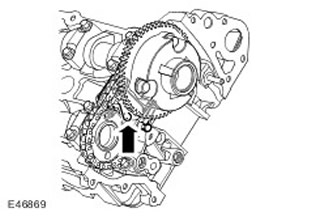
26. Screw in the bolts securing the left secondary timing chain tensioner. Tighten the bolts to 12 Nm.
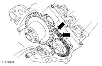
27.
NOTE: Lightly tighten the Torx head bolts to secure the sprocket to the camshaft.; the sprockets MUST move freely.
Install the left secondary timing chain and sprockets onto the camshafts. Install the Torx head bolts to secure the sprockets to the camshafts.
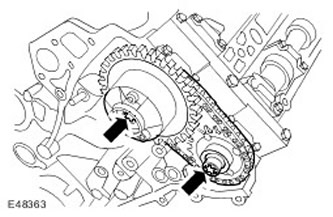
28. Tighten the secondary timing chain. Remove the metal rod.
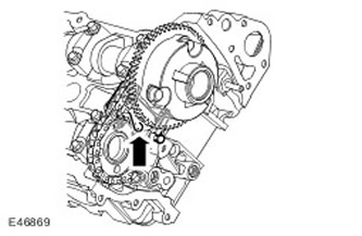
29. Repeat the operation for the right camshafts.
30.
NOTE: The picture shows the right side, the same for the left side.
Install the left primary timing chain. Make sure that the slack portion of the timing chain is on the tensioner side.
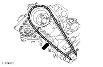
31. Install the left primary timing chain tensioner guide. Tighten the stud to 12 Nm.
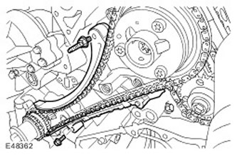
32.
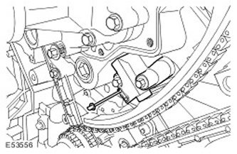
CAUTION: When compressing the timing chain tensioner, do not release the ratchet rod until the tensioner piston has fully entered the hole, otherwise the ratchet rod will be damaged.
Install the left primary timing chain tensioner.
- Using a 3mm diameter metal rod, hold the tensioner piston.
- Tighten the bolts to 12 Nm.
- Remove the metal rod.
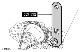
33.
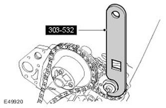
CAUTION: Apply counterclockwise force to the special tool to tighten the primary timing chain in its working area.
CAUTION: The intake camshaft sprocket bolt MUST be tightened before the exhaust camshaft sprocket bolt. Failure to do so will result in engine damage.
Install the special tool on the exhaust camshaft sprocket.
- Tighten the intake camshaft sprocket bolt to 20 Nm, then tighten it an additional 90 degrees.
- Tighten the exhaust camshaft sprocket bolt to 20 Nm, then tighten it another 90 degrees.
34. Install the left variable valve timing (VCT) control oil block.
- Install new O-rings.
- Tighten the new bolts to 22 Nm.
- Tighten the nut to 10 Nm.
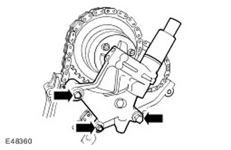
35. Install the right primary timing chain. Make sure that the slack portion of the timing chain is on the tensioner side.
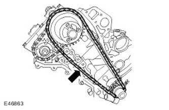
36. Install the right primary timing chain tensioner guide. Tighten the bolts to 12 Nm.
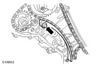
37.
CAUTION: When compressing the timing chain tensioner, do not release the ratchet rod until the tensioner piston has fully entered the hole, otherwise the ratchet rod will be damaged.
Install the right primary timing chain tensioner.
- Using a 3mm diameter metal rod, hold the tensioner piston.
- Tighten the bolts to 12 Nm.
- Remove the metal rod.
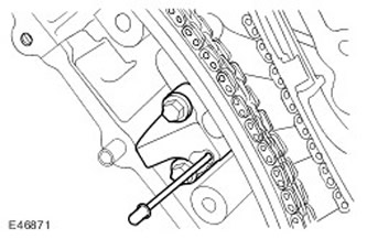
38.
CAUTION: Apply counterclockwise force to the special tool to tighten the primary timing chain in its working area.
CAUTION: The intake camshaft sprocket bolt MUST be tightened before the exhaust camshaft sprocket bolt. Failure to do so will result in engine damage.
CAUTION: Use new bolts.
Install the special tool on the exhaust camshaft sprocket.
- Tighten the intake camshaft sprocket bolt to 20 Nm, then tighten it an additional 90 degrees.
- Tighten the exhaust camshaft sprocket bolt to 20 Nm, then tighten it another 90 degrees.
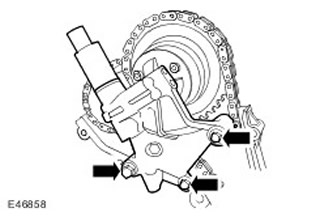
39. Install the right VCT oil control unit.
- Install new O-rings.
- Tighten the new bolts to 22 Nm.
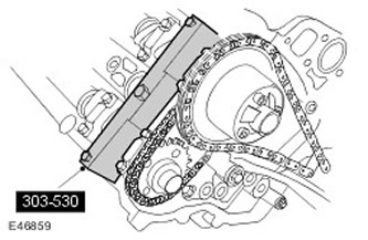
40. Remove the special tool from the left cylinder head.
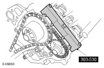
41. Remove the special tool from the right cylinder head.
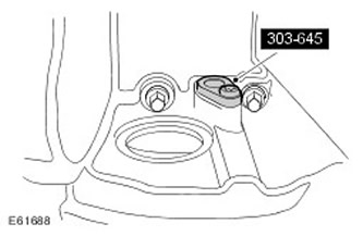
42. Remove the crankshaft locking tool. Unscrew the screw.
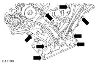
43. Install the front engine cover.
- Clean the mating surfaces of the elements.
- Apply a 3mm diameter, 12mm long bead of sealant to the 8 indicated locations.
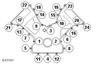
44. Tighten the bolts evenly and gradually in the sequence shown to 12 Nm.
45. Using special tools, install the front crankshaft oil seal.
- Clean the mating surfaces of the elements.
- Lubricate the seal with clean engine oil.
- Use the discarded crankshaft bolt together with the special tool.
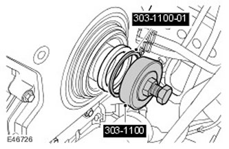
46. Using special tools, install the front crankshaft oil seal. Clean the mating surfaces of the elements.
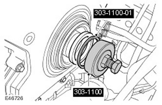
47. Install the crankshaft pulley. Lubricate the seal with clean engine oil.
48. Install the crankshaft pulley retaining ring.
49.
CAUTION: Before installing a new crankshaft pulley bolt, it is necessary to clean the threads in the crankshaft pulley.
Install the crankshaft pulley bolt, but do not tighten it.
50.
CAUTION: Under no circumstances should the crankshaft dowel pin, 303-645, be used to lock the crankshaft when performing the following procedure.
Using special tools, lock the crankshaft pulley. Tighten the crankshaft pulley mounting bolt to 380 Nm.
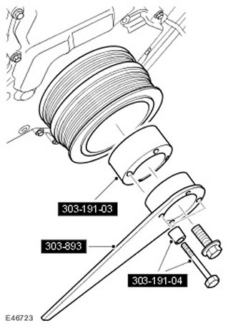
51. Remove the special tools.
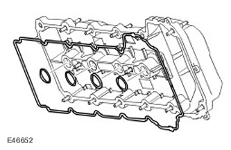
52. Install new seals in the spark plug holes in the cylinder head cover. Install a new cylinder head cover gasket.
53.
NOTE: Apply two beads of silicone gasket sealant as shown in the illustration. The beads of sealant should be 3 mm in diameter and 12 mm long. Install the cylinder head cover immediately after applying the sealant. The cylinder head cover must be installed directly onto the head without smearing the sealant on the gasket.
Install the cylinder head cover. Clean the mating surfaces of the elements.
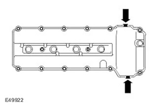
54. Screw in the cylinder head cover bolts.
- Screw in the cylinder head cover bolts in accordance with their previous location.
- Tighten the bolts in the order shown in the figure.
- Tighten the bolts to 12 Nm.
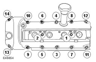
55. Install new seals in the spark plug holes in the cylinder head cover. Install a new cylinder head cover gasket.
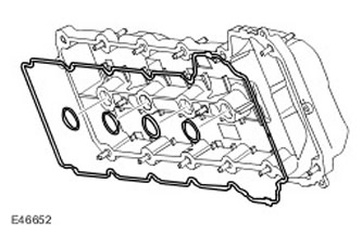
56.
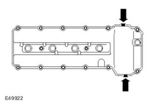
NOTE: Apply two beads of silicone gasket sealant as shown in the illustration. The beads of sealant should be 3 mm in diameter and 12 mm long. Install the cylinder head cover immediately after applying the sealant. The cylinder head cover must be installed directly onto the head without smearing the sealant on the gasket.
Install the cylinder head cover. Clean the mating surfaces of the elements.
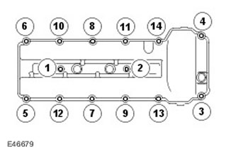
57. Screw in the cylinder head cover bolts.
- Screw in the cylinder head cover bolts in accordance with their previous location.
- Tighten the bolts to 12 Nm.
- Tighten the bolts in the order shown in the figure.
58. Install 8 direct ignition coils.
- Screw in 8 bolts.
- Tighten the bolts to 6 Nm.
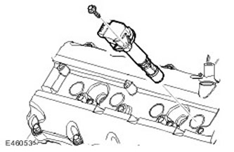
59. Install the generator support bracket.
- Clean the dowel pins.
- Clean the mating surfaces of the elements.
- Tighten the bolts to 45 Nm.
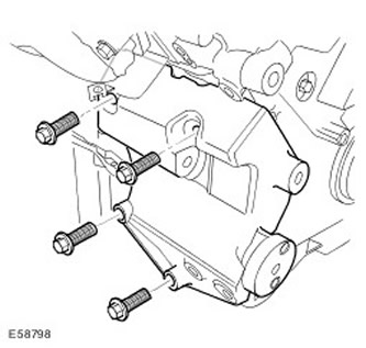
60. Install the air conditioner support bracket.
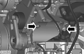
61. Install the coolant manifold. Tighten the bolts to 6 Nm.
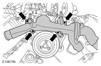
62. Install the coolant pump pulley. Tighten the bolts to 10 Nm.
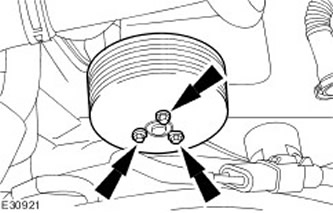
63. Install the auxiliary drive belt idler pulley. Tighten the bolt to 25 Nm.
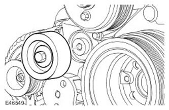
64. With assistance, install the intake manifold.
- Install the gaskets.
- Tighten the bolts evenly and gradually to 20 Nm.
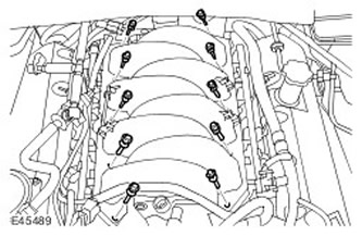
65. Install the purge valve.
- Secure the wiring harness with a clamp.
- Tighten the bolt to 6 Nm.
- Connect and secure the electrical connector.
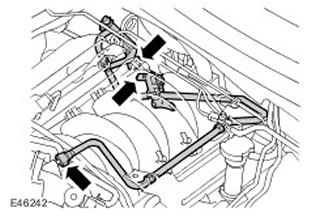
66. Connect the positive starter cable. Secure the cover.
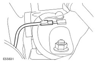
67. Connect the engine oil temperature and pressure sensors.
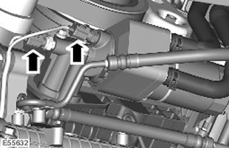
68. Install the generator.
- Clean the mating surfaces of the elements.
- Tighten the bolts to 48 Nm.
- Connect the generator electrical connector.
- Secure the clamps.
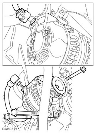
69. Install the crankshaft position (CKP) sensor electrical connector. Connect the CKP sensor electrical connector.
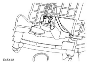
70. Install the power steering pump support bracket.
- Clean the mating surfaces of the elements.
- Tighten the bolts to 25 Nm.
- Clamp the transmission fluid cooler lines.
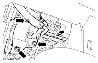
71. Connect and secure the CMP sensor electrical connectors. Repeat the operation on the right side.
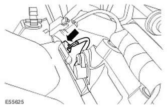
72.
NOTE: There may be some differences from what is shown in the pictures, but the basic information is correct.
Connect the electrical connector of the KS sensor.
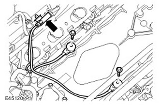
73. Connect the engine coolant temperature (ECT) sensor electrical connector.
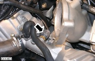
74. Connect the electrical connectors of the direct ignition coils.
- Install the clamps.
- Repeat the above procedure on the other side.
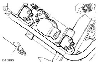
75. Connect the variable valve timing (VCT) solenoid electrical connector.
- Repeat the above procedure on the other side.
- Connect the ventilation hose to the cylinder head cover.
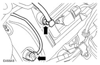
76. Connect the cylinder head ground electrical connector.
- Screw in the bolt.
- Fasten 3 clamps.

77. Install the direct ignition coil cover.
- Secure the clamps.
- Repeat the above procedure on the other side.

78. Remove the engine from the engine stand.
79. Install the engine.
Comments on this article