Removing
WARNING: If on a vehicle with variable valve timing (VCT) it is necessary to replace the cylinder head, before installing a new cylinder head, the embedded rivet of the oil line must be removed.
1. Disconnect the wire "masses" from the battery. For more information, refer to Specification
2. Remove the intake manifold. For more information refer to Intake Manifold Assembly (30.15.02)
3. Remove camshafts of the left number of cylinders. For more information refer to Left Camshafts (12.13.21)
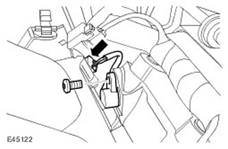
4. Remove the camshaft position sensor (SMR).
- Remove the Torx head screw.
- Disconnect the electrical connector.
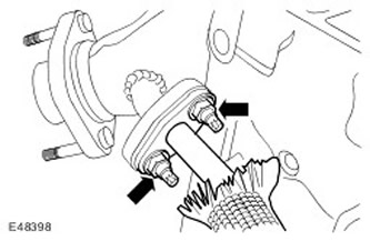
5. Disconnect the EGR tube flange from the exhaust manifold. Loosen 2 nuts.
6.
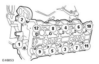
WARNING: Bolts can be reused twice. Mark the bolts to be reused by marking them with a center punch. If two punched points are visible on the bolts, discard the bolts.
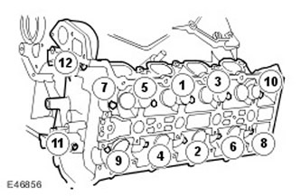
NOTE: Remove bolts in sequence shown.
Remove 12 cylinder head bolts.
7. Remove the left row cylinder head assembly. With assistance, remove the cylinder head.
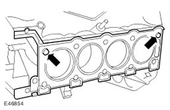
8. Remove the cylinder head gasket and discard it. Clean the dowel pins of the cylinder head.
9.
NOTE: Do not proceed with dismantling if the part is being removed only for access.
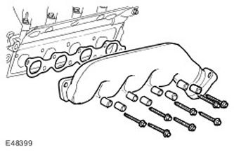
Remove the exhaust manifold.
- Remove 8 bolts.
- Discard the gasket and bolts.
Installation
1.
CAUTION: If the cylinder head needs to be replaced on a vehicle with a VCT system, the oil line rivet must be removed before installing the new cylinder head.
CAUTION: Remove all foreign particles from the cylinder head and cylinder head oil line.
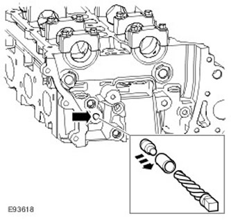
Vehicles equipped with VCT: Remove the blind rivet from the VCT oil line.
- Identify the VCT oil line and 8mm blind rivet.
- Using a suitable 3 mm punch, release the center of the blind rivet so that it disengages from the outside of the blind rivet.
- Using a suitable extraction tool, remove the remainder of the blind rivet.
2. Clean the contact surfaces of the parts.
3. Check up a surface of a head of cylinders regarding roughnesses in the central part and on corners.
4. Refer to the technical specifications for data on the deformation of the mating surface of the cylinder head. For more information refer to Specification.
5.
NOTE: If the cylinder head has a deformation greater than the maximum tolerance, the material of the cylinder head should be measured.
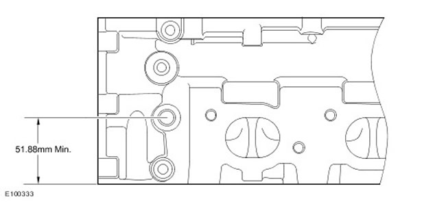
Measure the cylinder head material.
- Check the measurement from the center of the exhaust pin to the surface of the cylinder head as shown in the illustration.
- If the measurement is less than 51.88 mm, the cylinder head must be replaced.
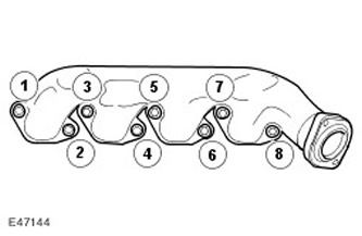
6. Install the exhaust manifold.
- Clean the contact surfaces of the parts.
- Install the gasket/heat shield.
- Tighten the heat shield bolt (tightening torque 25 Nm).
- Tighten the bolts evenly and progressively in the sequence shown (tightening torque 20 Nm).
7.
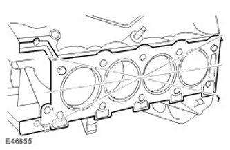
CAUTION: The cylinder head gasket must be installed on the cylinder block pins.
Install a new cylinder head gasket.
8. With assistance, install the cylinder head.
9.
NOTE: Tighten bolts 1 to 10 in the sequence shown.
Screw in bolts of fastening of a head of cylinders.
- Lubricate the new cylinder head bolts with clean engine oil.
- Tighten bolts 1 to 10 to 20 Nm.
- Tighten bolts 1 to 10 to 35 Nm.
- Tighten bolts 1 to 10 another 90 degrees.
- Tighten bolts 1 to 10 another 90 degrees.
- Tighten the bolts (M8) 11 and 12 (tightening torque 25 Nm).
10. Attach the EGR pipe and exhaust manifold flanges. Tighten nuts (tightening torque 25 Nm).
11. Install the CKP sensor.
- Tighten Torx Head Screw (tightening torque 7 Nm).
- Connect the electrical connector.
13. Reinstall the intake manifold. For more information refer to Intake Manifold Assembly (30.15.02)
14. Connect a wire of weight to the storage battery. For more information refer to Specification.
Comments on this article