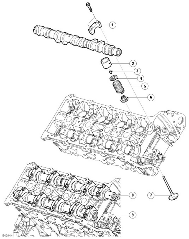
| Item name | Spare part number | Description |
| 1 | - | Camshaft bearing cap |
| 2 | - | valve tappet (without gasket) |
| 3 | - | Sleeve |
| 4 | - | valve spring cap |
| 5 | - | valve spring |
| 6 | - | valve stem seal |
| 7 | - | Valve |
| 8 | - | Inlet camshaft |
| 9 | - | Exhaust camshaft |
Cylinder heads
The cylinder heads of each row are not interchangeable. The cylinder head is fastened to the cylinder block with deep-seated bolts to reduce deformation. Two hollow pins ensure the alignment of each cylinder head with the cylinder block.
Spark plugs with a diameter of 14 mm, one plug per cylinder, are located in recesses on the axis of each cylinder head.
Engine mounting lugs bolt to cylinder heads - two at rear (one for each head) and one in front.
Camshaft covers
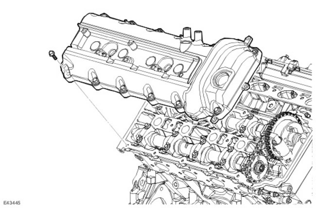
The camshaft covers are made of thermoplastic. The A bank camshaft cover has a part load breather hole. Bank B camshaft cover has a full load breather port and oil filler neck. Under the breather hole in each cap are identical oil separators. For more information refer to Electronic Engine Controls (303-14B Electronic Engine Controls - 4.4L) Between the camshaft covers and the cylinder heads, silicone rubber gaskets are located in the recess. Together with spacers and seals on the camshaft cover fasteners, they isolate the covers from direct contact with the cylinder heads, thus reducing noise levels.
Cylinder head gasket
The multi-layered steel cylinder head gasket has different coolant cuts for each cylinder, which ensures uniform flow of fluid.
Camshafts
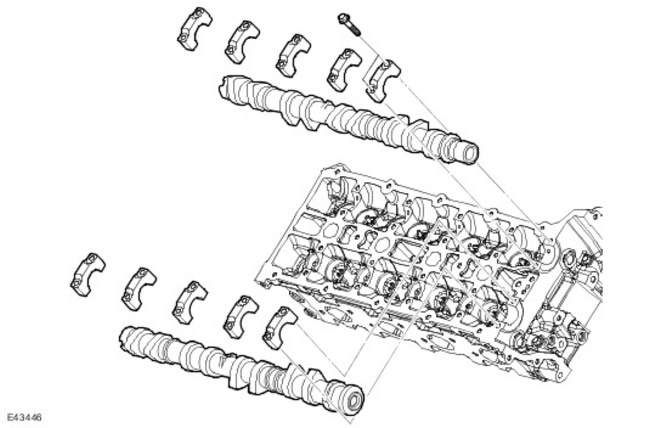
The camshafts are made of chilled cast iron. Five aluminum alloy caps hold each camshaft. On the top side of the caps, their numbers are marked - from 0 to 4 for the intake camshaft and from 5 to 9 for the exhaust camshaft.
Sensor Ring
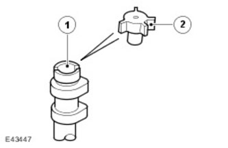
| Item name | Spare part number | Description |
| 1 | - | Inlet camshaft |
| 2 | - | Sensor Ring |
Rings for each camshaft position sensor are located at the rear of both camshafts. A flat machined surface near the front of both camshafts allows them to be locked when the valve timing is being adjusted.
Camshaft position sensor
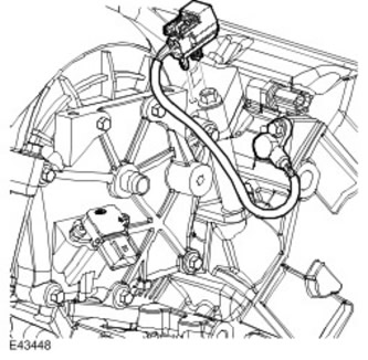
The camshaft position sensors are located in each cylinder head at the rear of the intake camshaft. The sensor is an electromagnetic sensor that generates a signal for the ECM containing information about the position of the camshaft. For more information refer to Electronic Engine Controls (303-14B Electronic Engine Controls - 4.4L)
Inlet and outlet valves
Each cylinder head has two overhead camshafts driving four valves per cylinder via solid aluminum alloy non-adjustable tappets.
Lightweight valve train ensures low fuel consumption and noise levels. Valve head diameter: 31mm exhaust and 35mm intake. All valves have a stem diameter of 5 mm; the seat and guide bushings are made of metal powders by sintering. Between the bushings, valve discs and spring seats are single valve springs on both the intake and exhaust valves. The valve stem seals are built into the spring seats.
ATTENTION: Due to some difference in length, the valves are not interchangeable between vehicles of different brands (Land Rover, Jaguar and Aston Martin).
Fuel injectors
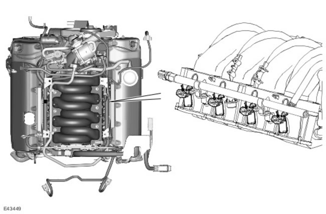
Eight fuel injectors with 12 nozzles and top fuel supply are installed on the fuel rails. The injector is unlocked by a solenoid valve controlled by the ECM. Two O-rings seal the contact between the fuel rail and each injector. The injectors deliver fuel to the rear of the intake valves. For more information refer to Electronic Engine Controls (303-14B Electronic Engine Controls - 4.4L)
Comments on this article