Special tool
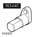 Valve timing tool 303-645 Valve timing tool 303-645 | 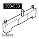 Camshaft Installation/Locking Tool 303-530 Camshaft Installation/Locking Tool 303-530 | 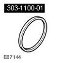 Adapter for crankshaft oil seal installation device 303-1100-01 Adapter for crankshaft oil seal installation device 303-1100-01 |
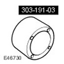 Adapter 303-191-03 Adapter 303-191-03 | 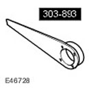 Crankshaft Pulley Locking Tool 303-893(LRT-12-080) Crankshaft Pulley Locking Tool 303-893(LRT-12-080) | 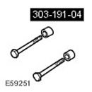 Bolts and spacers 303-191-04 Bolts and spacers 303-191-04 |
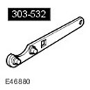 Timing Chain Tensioner Tool 303-532 Timing Chain Tensioner Tool 303-532 |
Disassembly
1. Remove the engine assembly. For more information, refer to Engine (12.41.01.99)
2. Secure the engine to the engine stand.
- Adjust the engine position on the engine stand.
- Adjust the position of the engine stand legs.
- Place the engine on an engine stand.
- Fully tighten the engine stand leg nuts.
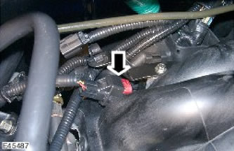
4. Remove the coolant manifold.
- Remove 4 bolts.
- Disconnect the electrical connector.
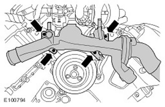
5. Move the wiring harness support bracket aside to gain access. Remove the 2 bolts.

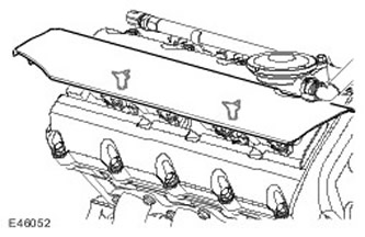
6.
NOTE: The picture shows the right side, the same for the left side.
Remove both direct ignition coil covers. Release from 2 clamps.
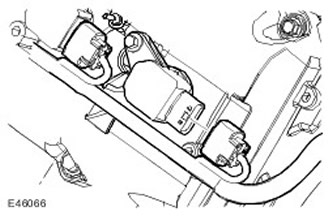
7.
NOTE: The picture shows the right side, the same for the left side.
Disconnect the electrical connectors of the 8 direct ignition coils (coils in the block with spark plugs).
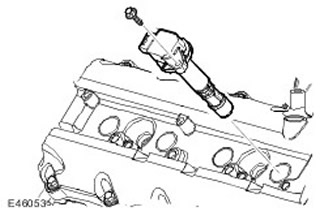
8. Remove 8 direct ignition coils. Unscrew 8 bolts.
9. Disconnect the ventilation hose from the cylinder head cover.
- Disconnect the variable valve timing (VCT) oil control solenoid electrical connector.
- Repeat the operation on the other side.
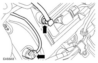
10. Disconnect the engine coolant temperature (ECT) sensor electrical connector.
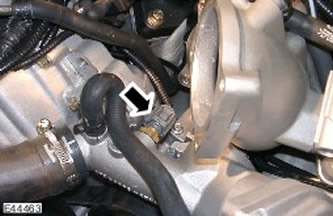
11. Disconnect the CMP sensor electrical connector. Repeat the above procedure on the right side.
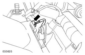
12. Disconnect the cylinder head ground electrical connector.
- Remove the bolt.
- Release the 3 clamps.
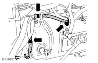
13. Disconnect the electrical connector of the knock sensors (KS).
14. Disconnect the purge valve from the support bracket.
- Disconnect the quick release coupling.
- Disconnect the electrical connector.
- Remove the bolt.
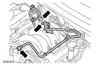
15. Release the 5 clamps of the air conditioner wiring harness.
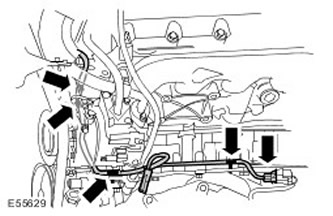
16. Remove the crankshaft position sensor (CSP).
- Disconnect the electrical connector.
- Remove the Torx head screw.
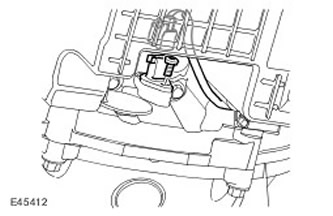
17. Remove the power steering pump support bracket.
- Remove 3 bolts.
- Loosen the transmission fluid cooler line clamps.
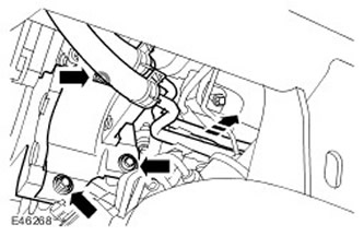
18. Remove the air conditioning compressor support bracket. Remove 2 bolts.
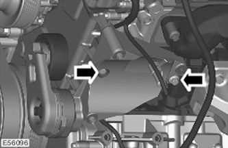
19. Disconnect the starter electrical connector.
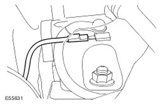
20. Disconnect the engine oil temperature and pressure sensors.
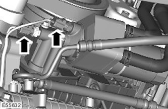
21. Disconnect the generator electrical connector.
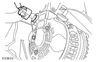
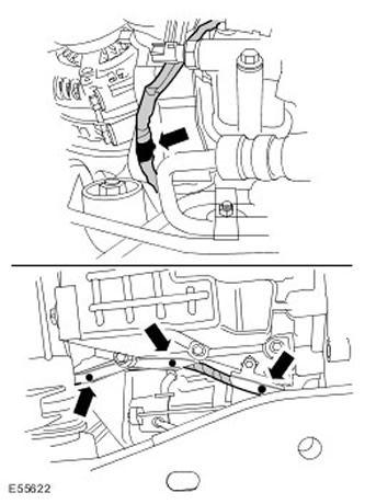
22. Release the 4 clamps securing the generator wiring harness.
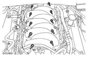
23. Remove 10 intake manifold bolts.
24.
CAUTION: Before disconnecting or removing components, clean the area around the contact surfaces and connections. To avoid contamination of the system, plug all open connections.
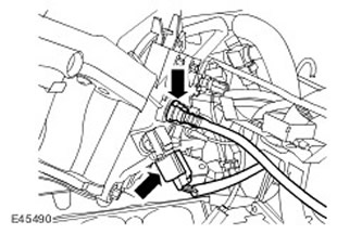
Remove the intake manifold.
- Disconnect the brake booster vacuum hose from the intake manifold.
- Discard the gaskets.
- Disconnect the manifold absolute pressure (MAP) sensor electrical connector.
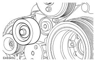
25. Remove the auxiliary drive belt idler pulley. Remove the bolt.
26. Remove the coolant pump pulley. Remove 3 bolts.
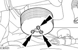
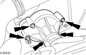
27. Remove the coolant pump.
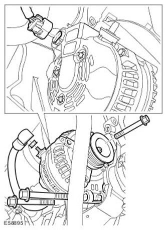
28. Remove the generator.
- Disconnect the electrical connector.
- Remove 3 bolts.
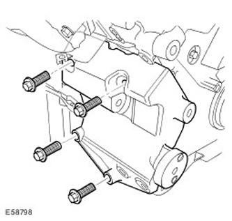
29. Remove the generator support bracket. Unscrew the 4 bolts.
30. Remove the dipstick and oil level indicator tube.
- Unscrew the nut.
- Discard the sealing ring.
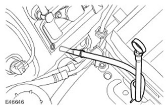
31. Remove the right cylinder head cover.
- Remove 14 cylinder head cover mounting bolts.
- Remove and discard the cylinder head cover gasket.
- Remove the seals from the spark plug holes in the cylinder head cover and discard them.
- Repeat the operation on the left side.
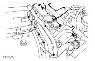
32. Remove the front engine cover.
- Release the engine wiring harness clamps.
- Remove 24 bolts.
- Remove the gasket and discard it.
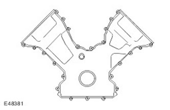
33. Turn the crankshaft so that the flats on the camshafts are parallel to the mating surfaces of the cylinder head.
34.
NOTE: The engine is now in the SAFE position.
Block the crankshaft.
- Install the special tool.
- Screw in the screw.
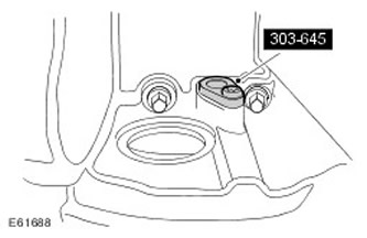
35. Remove the right VCT control unit.
- Remove 3 bolts.
- Remove the O-rings and discard them.
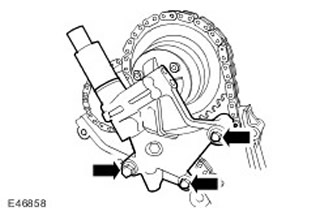
36. Install the special tool on the right cylinder head. Screw in 3 bolts.
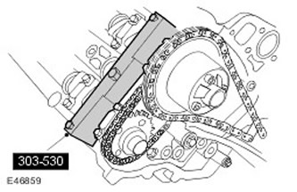
37. Remove the right primary timing chain tensioner. Remove 2 bolts.
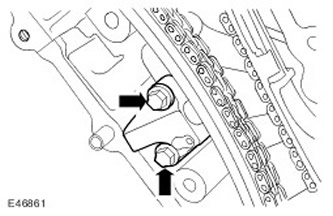
38. Remove the right primary timing chain tensioner guide. Remove the bolt.
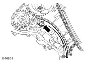
39. Remove the right primary timing chain.
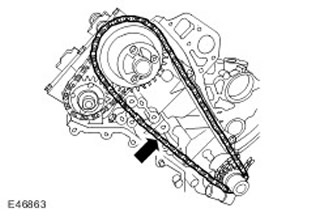
40. Remove the left VCT control unit.
- Remove 2 bolts.
- Unscrew the nut.
- Remove the O-rings and discard them.
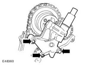
41. Install the special tool on the left cylinder head. Screw in 3 bolts.
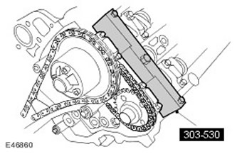
42. Remove the left primary timing chain tensioner. Remove 2 bolts.
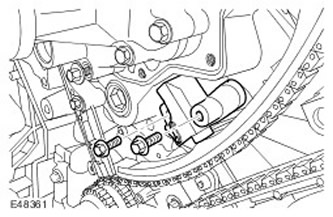
43. Remove the upper and lower guides of the left primary timing chain tensioner.
- Turn out the pin.
- Remove the bolt.
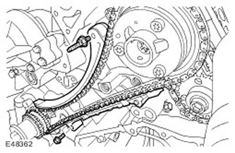
44. Remove the left primary timing chain.
45.
CAUTION: Discard bolts.
Remove the camshaft sprockets. Remove 2 bolts.
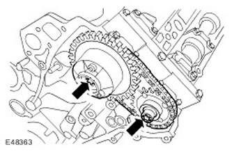
46. Remove the secondary timing chain tensioner and the secondary timing chain. Remove the 2 bolts.
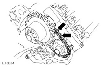
47. Remove the special tool from the left cylinder head. Remove the 3 bolts.
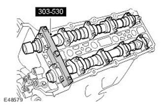
48.
CAUTION: Release the camshaft bearing caps evenly and gradually.
NOTE: Remove the camshaft bearing caps. Note: Remember their position, direction and marking. Each cap is marked with its position (number) and direction (arrow).
Remove the camshaft bearing caps. Remove 20 bolts.
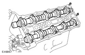
49. Remove the camshafts.
50. Install the special tool on the right cylinder head. Screw in 3 bolts.
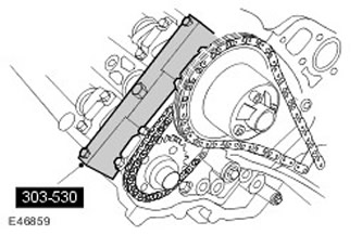
51.
CAUTION: Discard bolts.
NOTE: Left side shown, same for right side.
Remove the camshaft sprockets. Remove 2 bolts.
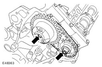
52.
NOTE: Left side shown, same for right side.
Remove the secondary timing chain tensioner and the secondary timing chain. Remove the 2 bolts.
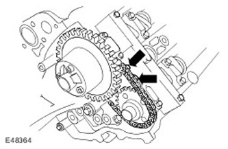
53.
CAUTION: Release the camshaft bearing caps evenly and gradually.
NOTE: Remove the camshaft bearing caps. Note: Remember their position, direction and marking. Each cap is marked with its position (number) and direction (arrow).
NOTE: Left side shown, same for right side.
Remove the camshaft bearing caps. Remove 20 bolts.
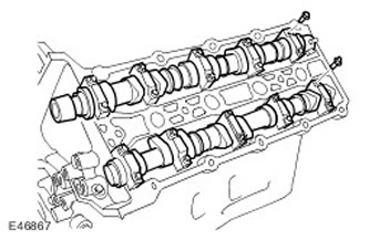
54.
NOTE: Bolts can be reused twice. Mark bolts to be reused by punching one dot in the center of the bolt. If bolts have two punched dots, discard the bolts.
Remove the left row cylinder head assembly.
- Remove 12 cylinder head bolts.
- With the help of another mechanic, remove the cylinder head.
- Remove the cylinder head gasket and discard it.
- Clean the cylinder head dowel pins.
- Clean the mating surfaces of the elements.
- Repeat the operation on the right side.
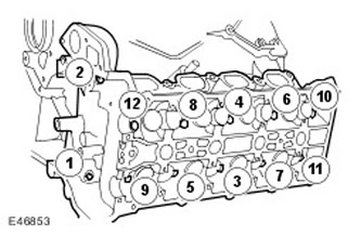
55. Remove the 4 bolts securing the engine support bracket to the cylinder block.
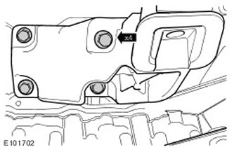
56.
CAUTION: Mark the location of the bolt.
Remove the starter. Remove the remaining starter bolt.
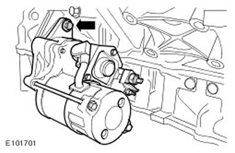
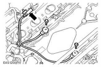
57. Remove KS.
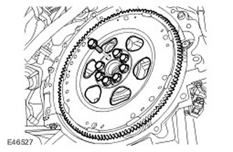
58. Remove the faceplate. Unscrew and discard the 8 bolts.
59.
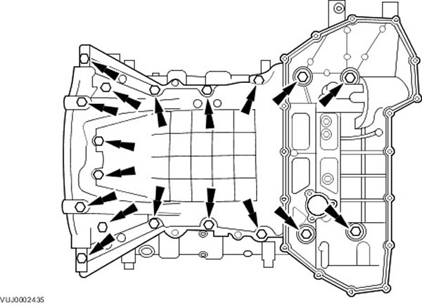
NOTE: There may be some differences from what is shown in the pictures, but the basic information is correct.
Remove the oil pan.
- Remove 18 bolts.
- Thoroughly clean all mating surfaces and reusable components and inspect them for damage.
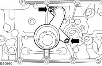
60. Remove the oil receiver intake pipe with the mesh filter assembly.
- Remove 2 bolts.
- Remove and discard the sealing ring.
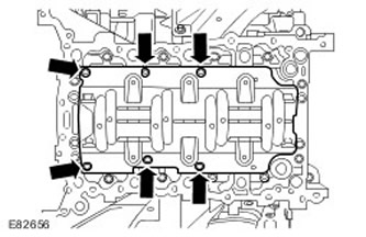
61. Remove the reflector plate. Unscrew 6 bolts.
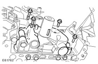
62. Remove the oil pump assembly.
- Remove 4 bolts.
- Remove the gasket and discard it.
- Clean the mating surfaces of the elements.
63. Remove the engine from the engine stand. With the help of a second mechanic, remove the engine block from the stand.
Comments on this article