Dismantling
1. Disconnect "negative" battery terminal.
2. Remove the rear timing belt cover.
ENGINE - MODIFICATION K, volume 1.8, Front exhaust camshaft oil seal, Rear timing belt cover.
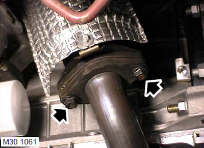
3. Turn away two nuts of fastening of a reception pipe to a final collector.
4. Remove the downpipe with gasket from the exhaust manifold.
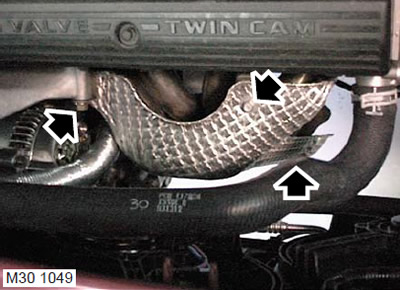
5. Models with air conditioning system: Remove the nut and 2 bolts securing the exhaust manifold heat shield.
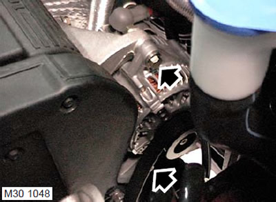
6. Air Conditioning Models: Remove the upper alternator mounting bolt and loosen the lower bolt. Move the generator forward to provide access to the heat shield.
7. Models with air conditioning system: Remove the heat shield.
8. Drain the engine coolant.
COOLING SYSTEM: MODIFICATION K, volume 1.8, ADJUSTMENTS, Coolant drain, system flushing and filling.
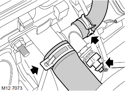
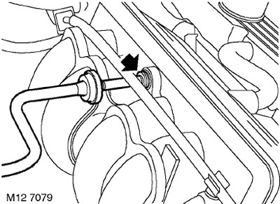
9. Turn away a collar and disconnect the top hose from an elbow branch pipe of system of cooling.
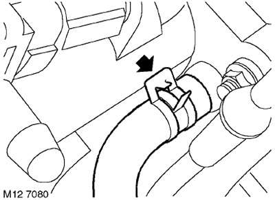
10. Loosen the clamp and disconnect the cooling system hose from the cooling system outlet.
11. Disconnect the block from the coolant temperature sensor.
12. Remove the valve cover.
ENGINE - MODIFICATION K, volume 1.8, Front exhaust camshaft oil seal, Valve cover gasket.
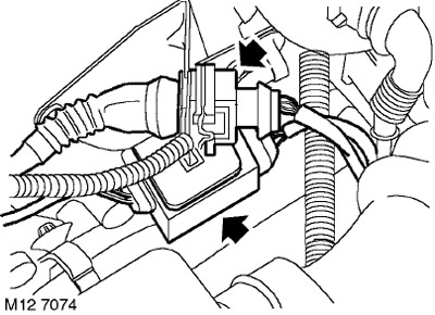
13. Release the camshaft position sensor connector from the bracket at the rear of the cylinder head.
14. Release and disconnect a socket of the oxygen gauge.
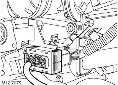
15. Disconnect the connector from the injector harness.
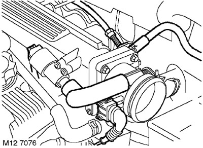
16. Disconnect the connector from the throttle position sensor.
17. Disconnect the connector from the idle speed controller.
18. Disconnect the bypass air hose from the idle speed controller and remove it from the throttle pipe.
19. Disconnect the idle speed control harness clamp from the bracket under the throttle pipe.
20. Loosen the clamp and disconnect the purge hose from the intake manifold.
21. Remove the throttle cable adjusting nut from the bracket.
22. Remove the cable from the damper control sector.
23. Lay out a rag to collect escaping fuel.
CAUTION: Fuel leakage is inevitable during this operation. Take safety precautions to prevent fire or explosion.
24. Disconnect the fuel supply hose from the fuel rail.
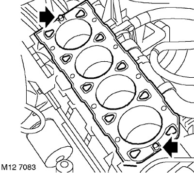
CAUTION: Always plug fittings and openings to keep dirt out of the system.
25. Press on the plastic shoulders of the quick connector and disconnect the brake booster vacuum hose from the intake manifold.
26. Loosen the clamp and disconnect the expansion tank hose from the intake manifold.
27. Temporarily install the gears on the camshafts, screw in the mounting bolts, but do not tighten them.
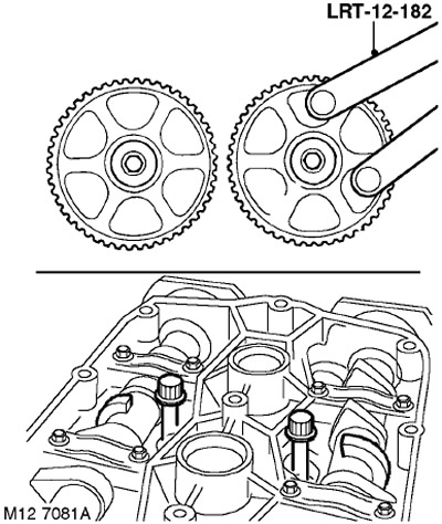
28. Using tool LRT-12-182, rotate the camshafts to gain access to the cylinder head bolts located under the inductive shaft positioners.
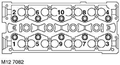
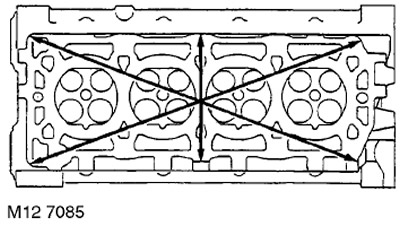
29. In the sequence shown in the figure, loosen the cylinder head bolts.
30. Take out bolts of fastening of a head of cylinders and expand them in that order in which they were on a head of cylinders.
31. With the help of a partner, remove the cylinder head.
CAUTION: When removing the cylinder head, be careful not to damage the oxygen sensor.
32. Remove and discard the cylinder head gasket.
WARNING: Removing the cylinder head bolts will result in "wedging" crankshaft. For this reason, the operations associated with the rotation of the crankshaft should be limited as much as possible. Do not rotate the crankshaft until the LRT-12-144 cylinder liners are installed.
33. Determine the type of installed pins: you should remove the nylon pins and install steel ones. The steel pins do not need to be replaced.
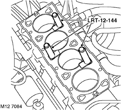
34. Install the LRT-12-144 cylinder liner mounts to the cylinder block and secure them with the cylinder head mounting bolts. The base of the cylinder liners must not protrude above the cylinder surface.
ATTENTION: The bolts used must be screwed into the same sockets in which they were on the assembled engine.
Installation
1. Turn out bolts from fastenings of liners of cylinders LRT-12-144 and remove fastenings.
CAUTION: Store the cylinder head bolts in the order in which they were on the assembled engine. Do not rotate the crankshaft after removing the cylinder liner fasteners. Do not apply force to the cylinder liners after removing their fasteners.
2. Clean the mating surfaces of the cylinder head and cylinder block.
3. Check that the channels of the cooling system and the lubrication system are clean.
4. Be convinced of absence of damages on the bottom plane of a head of cylinders and on the top plane of the block of cylinders. Particular attention should be paid to the condition of the lower plane of the cylinder head.
5. Check the flatness of the cylinder head for warping by laying a straight edge along the directions shown in the figure.
TECHNICAL CHARACTERISTICS, Engine - gasoline K1.8.
NOTE: The underside of the cylinder head may be ground as long as the head height remains within acceptable limits.
6. Thoroughly wash the cylinder head bolts, wipe them dry and lightly lubricate their threaded part and headrest with engine oil.
7. Carefully insert the bolts into their sockets in the order in which they were on the assembled engine, DO NOT RESET THE BOLT INTO THE SOCKET. Tighten each of the bolts to failure with finger force only.
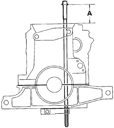
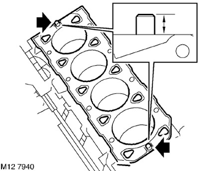
8. Measure the distance 'A' from the head of the bolt to the top plane of the cylinder block as shown in the figure:
- 97 mm: bolts are recyclable.
- Above 97 mm: new bolts must be used.
9. If the nylon pins were removed, then you need to clean their sockets and install new, steel pins.
10. The protrusion of the pins should be between 10 and 11 mm.
11. Temporarily install the gears on the camshafts, screw in and lightly tighten the bolts of their fastening.
12. Fit a new cylinder head gasket to the cylinder block with the 'TOP' mark facing up.
CAUTION: Gaskets must be installed dry.
13. With the help of a partner, install the cylinder head on the block so that the pins fit into the sockets.
14. Using tool LRT-12-182, rotate the camshafts to gain access to the cylinder head bolts located under the inductive shaft positioners.
15. Carefully insert the bolts into their sockets in the order in which they were on the assembled engine, DO NOT RESET THE BOLT IN THE SOCKET. Tighten the bolts by hand.
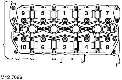
16. In the sequence shown in the figure, tighten the cylinder head bolts:
- Stage 1: 20 Nm.
- Tighten another 180°.
- Tighten another 180°.
WARNING: Do not turn bolts 360°. for one take.
NOTE: Use tool LRT-12-182 to rotate shafts and access bolt heads.
17. After completing the drawing of the cylinder head bolts, turn the camshafts so that the locating pin for the intake shaft gear is in position "4 hours", and graduation - "8 ocloc'k".
18. Hold the camshafts with the LRT-12-182 fork and remove the camshaft sprocket mounting bolts with washer.
19. Remove the camshaft gears.
20. Attach a hose to a broad tank and fix it with a collar.
21. Attach a hose of the vacuum amplifier of a brake system to an inlet collector.
22. Fasten the throttle control cable to the gas sector and the cable sheath to the bracket.
23. Attach the purge hose to the intake manifold and secure it with a clamp.
24. Attach the fuel supply hose to the fuel rail.
25. Connect the connector to the idle speed control and secure the harness with a clamp.
26. Install the bypass air hose on the idle air control and connect it to the throttle pipe.
27. Connect the connector to the coolant temperature sensor (ECT).
28. Connect the connector to the throttle position sensor.
29. Connect the connector to the injector harness.
30. Connect the oxygen sensor connector and secure it to the bracket.
31. Install the valve cover.
ENGINE - MODIFICATION K, volume 1.8, Front exhaust camshaft oil seal, Valve cover gasket.
32. Attach a hose of system of cooling to an elbow branch pipe and fix it with a collar.
33. Models with air conditioning system: Install the exhaust manifold heat shield.
34. Models with air conditioning system: Install the generator on the bracket and screw in the bolt. Tighten both alternator mounting bolts to 45 Nm.
35. Models with A/C system: Install the heat shield on the alternator mounting stud, install the nut and bolts. Tighten the nut to 25 Nm and the bolts to 10 Nm.
36. Wipe the exhaust pipe flange and mating surfaces of the exhaust manifold.
37. Having installed a new gasket, connect the exhaust pipe to the exhaust manifold, screw on the nuts and tighten them to a torque of 60 Nm.
38. Install the rear timing belt cover.
ENGINE - MODIFICATION K, volume 1.8, Front exhaust camshaft oil seal, Rear timing belt cover.
39. Adjust the throttle cable.
FUEL SUPPLY OF PETROL ENGINE, ADJUSTMENTS, Throttle control cable - check and adjustment: K1.8 engine.
40. Attach "negative" battery terminal.
41. Add coolant to the cooling system.
COOLING SYSTEM: MODIFICATION K, volume 1.8, ADJUSTMENTS, Coolant drain, system flushing and filling.
42. Add oil to the engine.
MAINTENANCE, MAINTENANCE, Engine oil and oil filter - K1.8.
Comments on this article