Contents: How to deactivate the SRS system ⇩ Installation ⇩ Precautions when checking SRS system…⇩ Transportation and storage ⇩ SRS Electrical Harnesses and…⇩ Inspecting the side impact sensor ⇩ Movable contact group ⇩
WARNING: Do not install a rear-facing child seat in the front passenger seat.
The SRS system contains components that, if handled improperly, may pose a hazard to service personnel. The following instructions and precautions are intended to familiarize service personnel with potential hazards and the importance of the operability of the SRS components installed in the vehicle.
WARNING: The following precautions MUST be observed when working on the SRS system:
- Always follow the rules for working with SRS system components.
- Personnel servicing SRS systems must be suitably qualified and familiar with safety precautions.
- Airbags contain extremely dangerous and flammable substances. Contact with water, acids or heavy metals may cause injury or explosion. Do not disassemble or expose to flame or electric current if the unit has failed.
- If the belt shows signs of wear or the seat belt system has been subjected to impact loads as a result of a collision, the seat belt system must be replaced.
- Before performing welding work on a vehicle equipped with the SRS system, the battery must be disconnected.
CAUTION: Do not expose air bags or seat belt pretensioners to temperatures above 85°C.
Please note that the instructions provided should not only be followed during direct repair of the SRS system. The same safety precautions should be observed when working on related systems and components located in close proximity to the SRS system components. The following systems and components are not a complete list of such systems and components:
- Driver's front airbag, rotary contactor
- Front passenger front airbag
- Front and rear side curtain airbag modules
- Seat belt pretensioners
- SRS Wiring Harnesses, Connecting Wires and Connectors
- Side airbags
How to deactivate the SRS system
Before working on the SRS system or in the immediate vicinity of its components, the system must be deactivated. To do this, perform the following steps:
- Disconnect the remote control.
- Disconnect the battery. The ground wire is connected first.
- Wait for 2 minutes. During this time, the SRS power supply circuit is discharged.
NOTE: The SRS system uses capacitors to power it, which ensure that the system will operate if the electrical system is damaged during an accident. Allow sufficient time (10 minutes) for the capacitors to fully discharge. This will prevent the system from operating accidentally.
Installation
To ensure reliable operation of the SRS system in the event of an accident, periodic inspection and maintenance are required. All SRS components must be carefully inspected before installation. Do not install components that show signs of rough handling, such as dents, cracks, or residual deformation.
WARNING: The reliability of the SRS system directly affects the passive safety of the vehicle. Strictly adhere to the following rules:
- Do not use the airbag cover to attach accessories or for any other purpose.
- Do not install used SRS components from other vehicles or attempt to repair SRS components.
- When repairing the SRS system, use only new genuine spare parts.
- Do not apply power to any SRS components unless specified in the appropriate inspection procedure.
- Special fasteners are required to install the airbag module - do not use other fasteners.
- When replacing an SRS component, be sure to use new fasteners and ensure that all fasteners are tightened to the specified torque.
When installing airbag units, make sure that interior trim parts do not interfere with the airbag deployment.
SRS system components must be free of oil or grease.
NOTE: After the pretensioners have deployed, the seat belts can be used as normal seat belts, but they must be replaced as soon as possible to restore proper SRS function. Do not use the seat belts if the retractor does not operate properly.
NOTE: If replacement of SRS components is required, the part number and bar code of the new part must be recorded.
Precautions when checking SRS system components
Airbags deploy at relatively low current levels, so always follow these instructions:
WARNING: Do not use multimeters or other multi-purpose equipment when testing SRS components. Use only Land Rover approved diagnostic equipment to diagnose system faults.
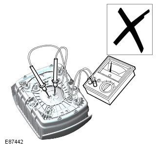
WARNING: Do not use multi-purpose diagnostic equipment to troubleshoot SRS harnesses that are still connected to the system components, as this may result in airbag deployment and injury.
Transportation and storage
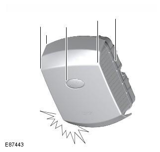
When handling SRS components, follow the instructions below:
- Do not throw SRS components. The SRS electronic unit requires particularly careful handling due to its increased sensitivity to impacts. The airbags and seat belt pretensioners may be activated by a strong impact.
- Do not wrap your hands around the airbags. When transporting airbags, hold them by the cover, with the cover in the highest position and the base facing away from your body.
- Do not transport airbags or seat belt pretensioners in the passenger compartment of the vehicle. Airbag modules or seat belt pretensioners may only be transported in their original packaging in the luggage compartment of the vehicle.
- Do not attach any objects to the airbag cover or the trim that covers the airbags. Do not place any objects on top of the airbags.
- System components should be stored in a cool, dry and safe area.
- Do not apply lubricants or cleaning agents to the seat belt pretensioners. This may damage the pretensioners.
- Always store air bags face up. If an air bag is stored face down, accidental deployment could cause serious injury.
- Store the side curtain airbag in its original packaging until it is ready to be installed on the vehicle. Store the removed side curtain airbag in the empty packaging.
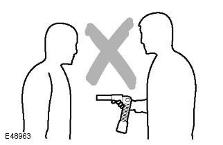
When handling the curtain air bag module, hold it by the inflator housing, NOT by the air bag. Do not wrap your fingers around the inflator when carrying. Do not sling the air bag over your shoulder or around your neck. Carry the pretensioners by the piston tube with the open end of the tube facing the ground and the opposite end of the tube away from your torso. Do not cover the open end of the piston tube. DO NOT hold the pretensioners by the cable or the mounting bracket. Do not point the piston tube toward your torso or toward another person.
Airbags and seat belt pretensioners are classified as explosives. For overnight or longer storage, they must be placed in a steel safe that has the required level of protection and is registered with the local authorities.
Store airbags or seat belt pretensioners only in a specially designated place. If there is no specially equipped storage place, they should be stored in a locked trunk of the car. The production manager must be informed about this.
CAUTION: Improper storage may damage the airbags and render them unusable. If there is reason to believe that the airbag is faulty, it must be replaced. For activation and disposal of the airbag, refer to the relevant section of the Manual.
SRS Electrical Harnesses and Connectors
When working with SRS wiring harnesses, follow these instructions:
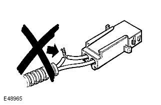
- Do not modify, extend, or repair the SRS harness in any way.
- Do not install potential sources of electromagnetic interference (mobile phone, radio or entertainment equipment) in the immediate vicinity of the SRS harness. If you need to install such equipment, consult a specialist.
NOTE: The wires in the SRS harnesses can be identified by the yellow color of the outer insulation (sometimes black insulation with a yellow stripe is used).
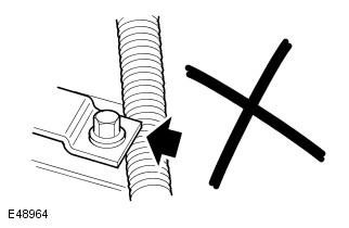
WARNING: After installation, always check that the SRS harnesses are routed correctly. Avoid pinching or damaging the SRS harnesses during installation.
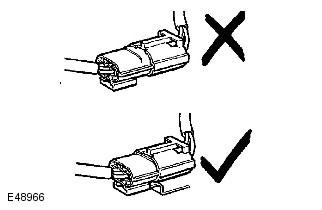
WARNING: Do not allow connectors to hang freely or install SRS components without securing them to the vehicle body. There should be no friction points on moving vehicle body parts after installation.
Inspecting the side impact sensor
After any side impact of the body, both side impact sensors must be inspected. The side impact sensor must be replaced if signs of damage are visible.
CAUTION: When performing body repair or painting work in the immediate vicinity of impact sensors, exercise extreme caution. Avoid direct contact between impact sensors and connecting harnesses with heat guns, welding and painting equipment. Beware of damaging the sensor or wiring harness during assembly of units.
Movable contact group
CAUTION: Always follow the installation and inspection procedures for the sliding contact group as described in the SRS repair section. To ensure reliable operation of the system, all operations must be carried out in strict accordance with all safety requirements and installation rules. Observe the following precautions:
- Do not unlock or rotate the sliding contact assembly when it is removed from the vehicle.
- Do not turn the wheels if the movable contact group is removed from the vehicle.
- The contact coil may only be removed and installed in the central position, with the front wheels in the forward motion position. The removal and installation procedure is discussed in the SRS repair section.
- When installing a new contact spiral, make sure that the locking protrusion that fixes the position of the spiral when turning the steering wheel is not broken. Otherwise, the contact spiral must not be used.
Comments on this article