Repair
Please note: repair of the mechanism is not permitted during the warranty period. Assembly and disassembly of the mechanism must be carried out in absolute cleanliness.
1. Remove the steering gear from the vehicle.
2. Drain the working fluid from the mechanism:
- a) unscrew the plug and drain screw.
- b) rotate the shaft in both directions, drain the liquid.
3. Rotate the retaining ring so that one end extends 12 mm beyond the access hole. Using a suitable pin, press the ring through the access hole until it exits the housing groove.
4. Remove the ring using a screwdriver.
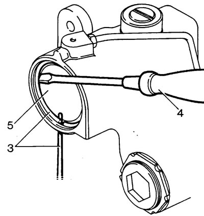
5. Turn the input shaft to the left stop (left-hand drive models) or to the right stop (right-hand drive models) and use the mechanism's piston to push out the lid. Turn the shaft in the opposite direction until it stops.
6. Remove the rack adjuster cover mounting screw.
7. Remove the rack adjuster and cover.
8. Loosen the sector shaft adjustment lock nut.
9. Unscrew the 4 bolts of the sector shaft cover.
10. Unscrew the sector shaft adjustment screw until the cover comes out of the housing.
Note: The threads of the sector shaft adjustment screw are coated with sealing compound.
11. Remove the sector shaft.
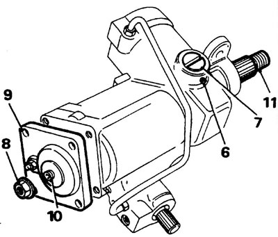
12. Insert a suitable bolt into the rack piston and remove the piston.
13. Remove the mud guard from the input shaft.
14. Using the LRT-57-007 key, loosen the lock nut of the worm adjustment unit.
15. Using the LRT-57-006 key, unscrew the worm adjuster.
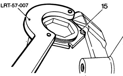
16. Tap the end of the splined shaft to release the bearings.
17. Remove the thrust ring and separator with bearing balls.
18. Remove the steering gear valve assembly and worm.
19. Remove the lower thrust bearing and adjusting washers.
Note: Checking the worm housing and bearings is difficult.
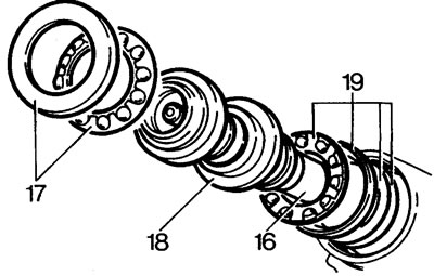
Steering gear seals
20. Remove the retaining rings, seals and the sector shaft oil seal.
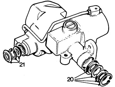
Caution: The sector shaft bearings cannot be removed. If the bearings are defective, replace the steering gear housing.
21. Remove the boot, retaining ring and input shaft seal.
Examination
Piston
22. Discard all rubber and plastic piston seals.
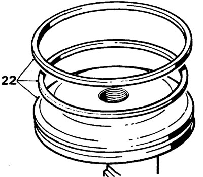
Note: The rubber seal is located behind the plastic one.
Steering gear housing
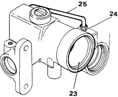
23. Inspect the housing for scratches and burrs on the rack piston surface.
24. Inspect the feeding tube.
25. Install a new feed tube if necessary. Tightening torque 22 Nm.
Sector shaft
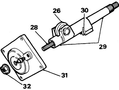
26. Make sure there is no lateral play in the roller.
27. If there is lateral clearance, install a new shaft.
28. Check the condition of the adjustment unit threads. Check the axial clearance in the adjustment unit. If the gap is more than 0.15 mm, replace the adjustment unit.
29. Check the bearing seats. If there is significant wear, replace the sector shaft.
30. Check the condition of the sector teeth.
Sector shaft cover
31. Inspect the cover and bearing. If there are any defects in the parts, the steering mechanism as a whole will have to be replaced; repairs are not provided.
32. The lock nut of the sector shaft adjustment unit must be replaced with a new one during installation.
Valve-worm assembly
33. Check the bearing seats. No wear or scratches allowed.
34. Check the condition of the worm. No wear or scratches allowed.
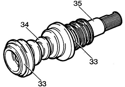
35. Check the condition of the torsion bar and its engagements: there should be no play in the engagements of the torsion bar with the input shaft. Otherwise, replace the entire assembly.
36. Check the condition of the valve rings. The rings must be free of burrs and scratches and rotate freely in the grooves.
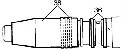
37. If necessary, install new rings using the LRT-57-019 expander. Remove the rings carefully to avoid damaging the grooves without the use of special tools.
38. After installing the valve rings, they must be crimped using the LRT-57-020 crimper.
Thrust bearings
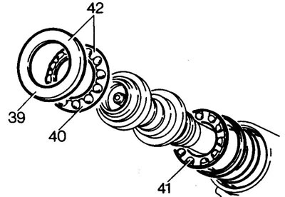
39. Check the condition of the bearing races.
40. Check the condition of the balls.
41. Check the reliability of the installation of the balls in the separator.
42. If the bearing is not suitable for installation, replace the entire unit.
Overlay and rack adjuster
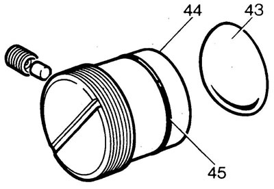
43. Check the condition of the lining, no chips are allowed.
44. Check the seat of the lining in the regulator.
45. Install a new sealing ring on the regulator.
Rack and piston
46. Check the condition of the rack teeth (wear and tear, chips).
47. Check the condition of the contact surface of the rack adjuster pad. Wear and tear are not allowed.
48. Check the outer diameter of the rack piston for burns or damage.
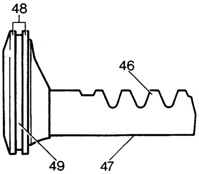
49. Check the condition of the piston seal grooves.
50. Install new piston seals. Heat the plastic ring in water before installation.
51. Install the rack and piston into the housing.
Assembly
Note: Before installing the seals, lubricate them with working fluid.
Sector shaft seal
52. Install the oil seal with the sealing lip towards the housing.
53. Install the intermediate washer.
54. Install the boot with the sealing lip away from the housing.
55. Install the retaining ring.
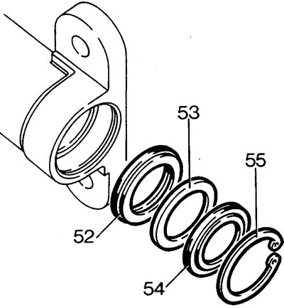
Installing the valve and worm
56. Install the adjusting washer and the inner bearing race.
Note: If the old adjusting washer is lost, install a 0.76mm thick washer.
57. Install the separator and the second race of the inner bearing.
58. Install the valve and worm assembly.
59. Install the treadmill and outer bearing separator.
60. Install the second outer bearing race.
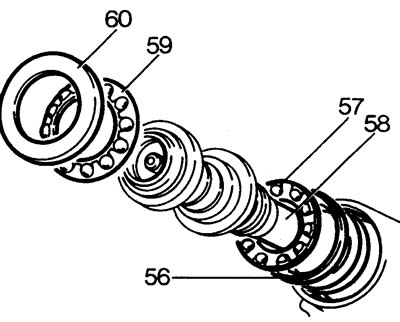
61. Install a new worm adjuster O-ring.
62. Screw the regulator into the housing by hand.
63. Screw on the regulator lock nut.
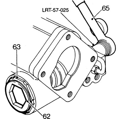
64. Tighten the adjuster until the axial clearance is taken up. Make sure the bearings are seated correctly.
65. Using a torque wrench and the LRT-57-025 head, measure the worm torque.
66. Turn the regulator to adjust the bearing preload until the turning torque is 0.56 N·m.
67. Loosen the worm adjuster by 0.25 turns, tighten the adjuster until the torque is 0.21 - 0.34 N·m. Tighten the lock nut to a torque of 100 N·m. Use adjuster keys LRT-57-006 and lock nuts LRT-57-028.
Installing the rack and piston
68. To facilitate installation, tighten a suitable bolt into the piston.
69. Insert the rack into the housing so that the piston goes to a depth of 70 mm.
Installing the sector shaft
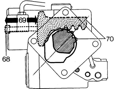
70. Using the LRT-57-021 oil seal protector, install the sector shaft as shown in the figure, engage the shaft with the rack by slightly turning the shaft.
Installing the rack regulator
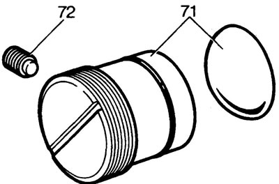
71. Install the regulator cover onto the rack, tighten the regulator until it touches the cover. Unscrew the regulator half a turn.
72. Install a new nylon insert into the regulator screw and tighten the screw by hand.
Installing the sector shaft cover
73. Install a new sealing ring on the cover.
74. Install the cover on the body, align the holes for installing the mounting bolts.
75. Press the cover until the gap between the adjusting screw and the sector shaft is selected.
76. If there is a gap between the cover and the body, unscrew the adjusting screw. Tap the lid until it is fully seated in the housing.
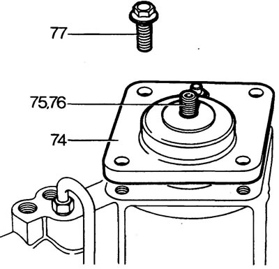
Note: Before tightening the cover mounting bolts, check the freedom of rotation of the sector shaft. If there is resistance to rotation, turn the adjusting screw two turns clockwise.
77. Tighten the cover mounting bolts to 75 Nm.
Installing the cylinder cover
78. Install a new sealing ring on the cover.
79. Remove the auxiliary bolt from the piston used when installing the rack.
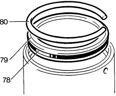
80. Install the retaining ring so that one end of it extends 12 mm beyond the technological hole.
Sector shaft adjustment
Note: Install the bipod and remove the mounting nut before selecting the clearance between the bipod and the steering shaft.
81. Rotate the input shaft to the inner stop (to the left stop (right-hand drive models) right stop (left-hand drive models)). Turn the input shaft in the opposite direction by two full turns - now the worm will be in the central position.
82. The mechanism is ready for adjustment.
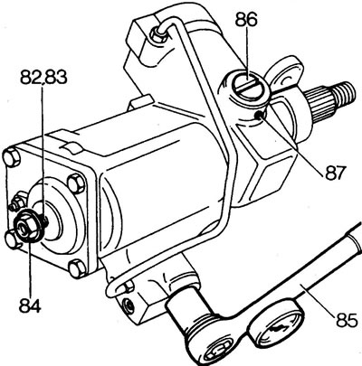
83. While holding the input shaft, rock the pitman arm to determine if there is clearance in the engagement. While continuing to swing the bipod, rotate the sector shaft adjusting screw until the gap is selected.
84. Tighten the adjusting screw lock nut.
Note: When making adjustments, the steering gear must be in the central position.
85. Check the crankshaft torque: install a torque wrench and LRT-57-025 head on the input shaft. Adjust the preload so that the shaft breakaway torque from the center position exceeds the rotation torque after one and a quarter turns by 0.34 N·m (in both directions). Tighten the adjusting screw lock nut to 60 Nm.
Rack adjustment
86. By turning the rack regulator, increase the torque of the mechanism (see paragraph 85) by 0.23-0.34 N·m. The total cranking torque should not exceed 1.35 N·m.
87. Secure the regulator with a screw, tightening torque of the screw is 5 Nm.
Checking the maximum cranking torque
Rotate the input shaft from lock to lock. The maximum torque should occur at the central position of the mechanism and decrease equally at the stops.
The above condition is determined by the thickness of the adjusting washer installed under the worm bearing. Typically, the factory-installed washer will provide the required adjustment even after individual parts have been replaced.
88. Install the steering gear with the input shaft towards the operator. Turn the intake shaft counterclockwise until it stops.
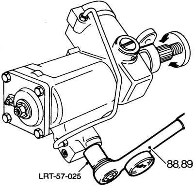
89. Measure the torque when approaching the limiters.
90. Check the equality of the steering gear turns from the center to both stops.
Adjustment
91. Mark the position of the mechanism at which the maximum torque is achieved. If the maximum moment does not occur at the central position, then:
- increase the thickness of the washer if the mechanism does not reach the central position;
- reduce the thickness of the washer when the mechanism passes through the center position.
Note: A 0.07mm change in washer thickness results in a 0.25 shaft revolution change in peak torque.
Caution: When disassembling the mechanism, do not damage the seals.
Input shaft seal
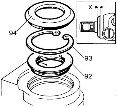
92. Install the oil seal with the sealing lip towards the housing. For installation, use the LRT-57-016 safety sleeve and LRT-57-026 mandrel. Press the oil seal to a depth of 4.75-5.00 mm from the housing plane.
93. Install the lock washer.
94. Lubricate the boot seal with PTFE grease. Install the boot using the LRT-57-027 tool. When properly installed, the boot edge should protrude from the housing by 4.0-4.5 mm, dimension "X".
The source of the article is located on the website: LRMAN.ru
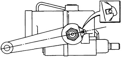
95. Remove the bipod. Lubricate the knuckle shaft boot with PTFE grease and install the boot.
96. Align the hole in the bipod with the hole in the mechanism body, install the bipod and a new lock washer. Tighten the mounting nut to 176 N·m and bend the edge of the washer onto the face of the nut.
97. Install the steering gear on the vehicle.
Comments on this article