Contents: Dismantling ⇩ Installation ⇩
Dismantling
1. Secure the hood in a vertical position.
2. Disconnect the negative battery terminal.
3. Remove the engine soundproofing cover.
ENGINE KV6 - MODIFICATION K, Camshafts of the left cylinder head, Soundproofing engine casing.
4. Remove the transfer case (IRD).
TRANSFER CASE, REPAIR WORK, Transfer case: models with KV6 engine.
TRANSFER CASE, REPAIR WORK, Transfer case: models with KV6 engine.
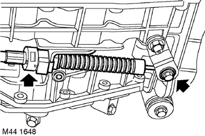
5. Loosen the nut securing the selector cable to the gearbox lever.
6. Remove the retainer securing the cable sheath to the bracket on the gearbox, remove the cable and the cable mounting sleeve on the lever.
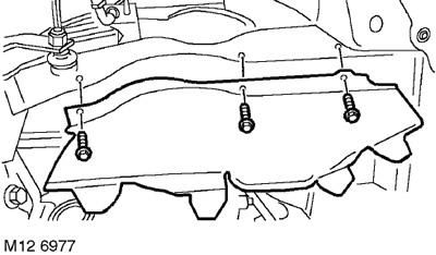
7. Unscrew the 3 bolts securing the left mudguard panel and remove the panel.
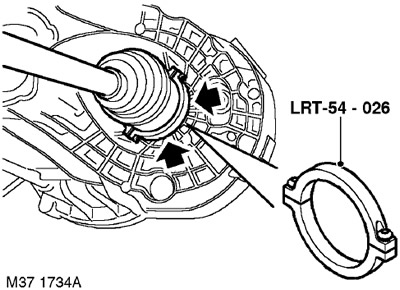
8. Install the LRT-54-026 tool onto the drive shaft inner joint. Use a lever to release the inner joint from the gearbox.
9. With the help of a partner, move the hub outward and remove the drive shaft from the gearbox.
CAUTION: When removing the drive shaft, be careful not to damage the oil seal.
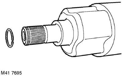
10. Remove and discard the drive shaft retaining ring.
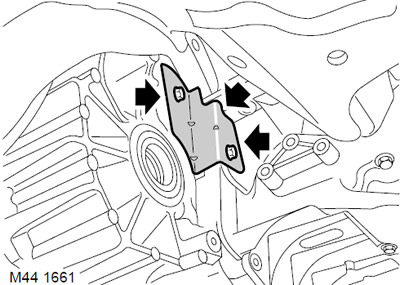
11. Remove the two bolts securing the torque converter hatch cover.
12. Remove the hatch cover.
13. Mark the relative positions of the drive disk and torque converter for subsequent assembly.
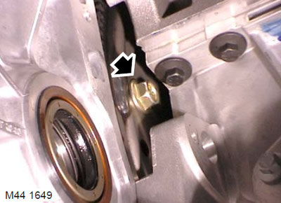
14. Unscrew the 4 bolts securing the drive disk to the torque converter.
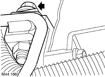
15. Unscrew the bolt securing the bracket of the cooling system hose going to the transfer case. Remove the bracket.
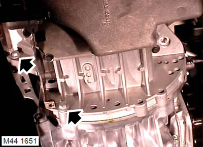
16. Unscrew the 2 bolts securing the gearbox to the engine.
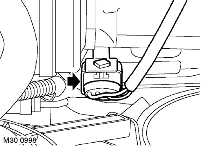
17. Release the oxygen sensor connector from the bracket on the left valve cover, disconnect the connector.
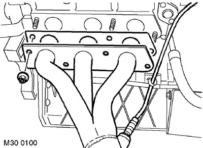
18. Unscrew the 4 nuts securing the left exhaust manifold to the cylinder head.
19. Remove the exhaust manifold and discard its gaskets.
20. Place a container to collect the leaking liquid.
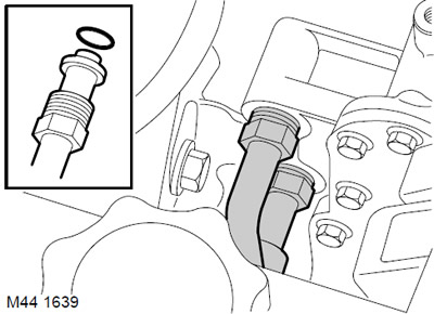
21. Disconnect the 2 fittings from the heat exchanger and discard the O-rings.
CAUTION: Always plug the fittings and holes to protect the system from dirt.
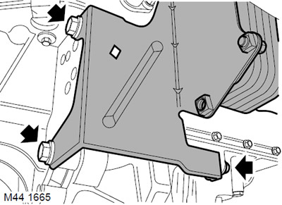
22. Unscrew the 3 bolts securing the heat exchanger bracket.
23. Move the heat exchanger to the side.
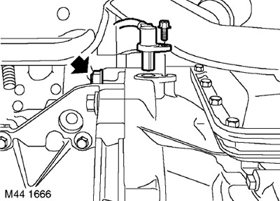
24. Loosen the bolt securing the crankshaft position sensor to the gearbox, release the sensor and move it to the side.
25. Unscrew the bolt and nut securing the gearbox to the engine, located next to the crankshaft position sensor.
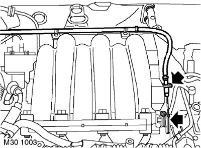
26. Disconnect the cable sheath from the bracket and disconnect the cable from the sector on the throttle pipe (with mechanical control of the valve).
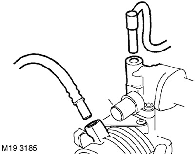
27. Squeeze the shoulders and disconnect the 2 ventilation tubes from the throttle body (if there are ventilation tubes).
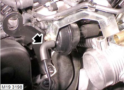
28. Vehicles with cruise control: Disconnect the vacuum hose from the cruise control actuator.
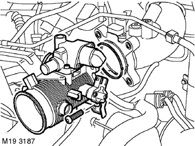
29. Unscrew the 4 bolts securing the throttle pipe, remove the throttle pipe and move it to the side.
Shown is a throttle body for vehicles other than the North American market.
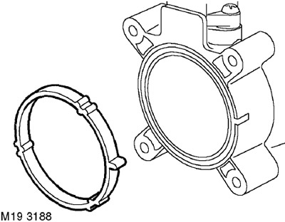
30. Remove the O-ring from the throttle body and discard it.
31. Remove the starter.
ENGINE STARTING AND BATTERY CHARGING SYSTEM, REPAIR WORK, Starter - KV6 engine.
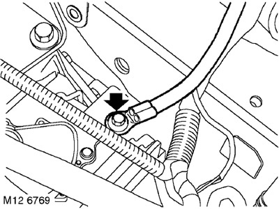
32. Unscrew the bolt securing the engine ground bus.
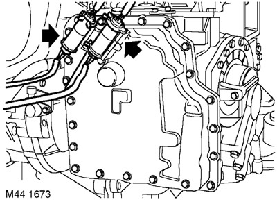
33. Release the connectors from the spring latches on the bottom of the box.
34. Disconnect the 2 transmission harnesses from the main engine harness connectors.
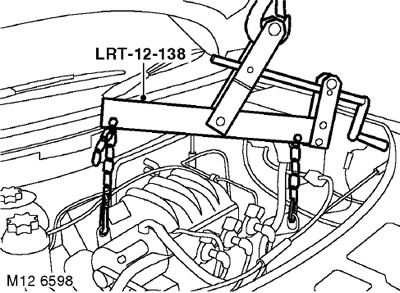
35. Attach the LRT-12-138 adjustable crosshead hoist to the engine.
36. Raise the hoist to relieve the load on the engine mounts.
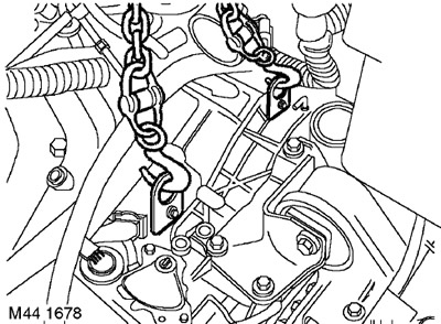
37. Attach the lifting eyes to the gearbox.
38. Attach the rigging equipment to the eyes.
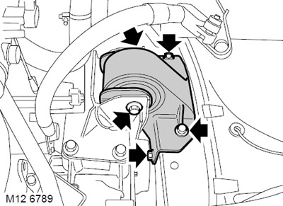
39. Remove the through bolt securing the left engine support to the gearbox.
40. Unscrew the 4 screws securing the left support to the body and remove the support.
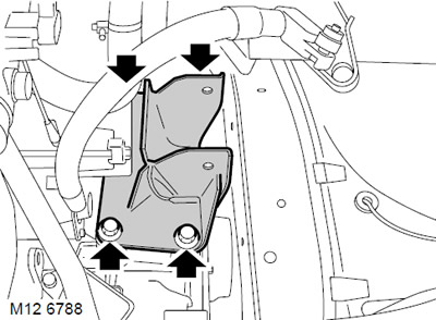
41. Unscrew the 4 bolts securing the left support bracket to the gearbox and remove the bracket.
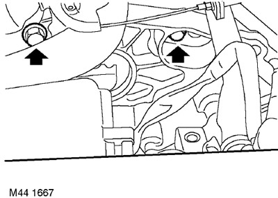
42. Remove the 2 upper transmission-to-engine mounting bolts.
43. Release the gearbox from the two guide pins.
44. Lower the gearbox to the floor.
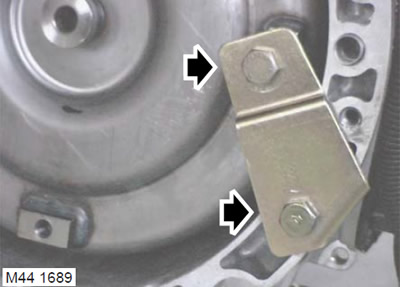
45. Install the torque converter retaining plate and secure it with screws.
Installation
1. Remove the torque converter retaining plate.
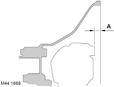
2. Check that the torque converter is fully seated on the oil pump drive by measuring dimension 'A' shown in the figure. Dimension A = 4 mm.
3. Wipe the mating surfaces of the engine and gearbox, the dowel pins and the dowel seats.
4. Install the gearbox.
5. Screw in the gearbox mounting bolts to the engine and tighten them to a torque of 85 Nm.
6. Install the left bracket on the gearbox, screw in the bolts and tighten them to a torque of 85 Nm.
7. Install the left support on the body, screw in the bolts and tighten to a torque of 48 Nm.
8. Position the gearbox bracket against the left support, insert the through bolt and tighten it to 100 Nm.
9. Remove the rigging chains.
10. Unscrew the bolts and nuts that secure the lifting eyes to the gearbox and remove the lifting eyes.
11. Connect the connectors to the main harness.
12. Secure the connectors in the spring clips.
13. Install the engine ground busbar and secure it with the bolt.
14. Reinstall the starter.
ENGINE STARTING AND BATTERY CHARGING SYSTEM, REPAIR WORK, Starter - KV6 engine.
15. Wipe the mating surfaces of the throttle body and intake manifold.
16. Install a new gasket on the intake manifold.
17. Install the throttle body onto the intake manifold, screw in the bolts and tighten them to 7 Nm.
18. Secure the throttle control cable to the gas sector and the cable casing to the bracket (for mechanical throttle control).
19. Connect the hose to the cruise control actuator.
20. Connect the ventilation hoses (if installed) to the throttle body.
21. Adjust the throttle control cable (if mechanical control).
FUEL SUPPLY SYSTEM OF GASOLINE ENGINE, ADJUSTMENTS, Throttle control cable - checking and adjustment: KV6 engine.
22. Wipe the crankshaft position (CKP) sensor and mating surfaces.
23. Install the crankshaft position sensor, screw in its mounting bolt and tighten to a torque of 9 Nm.
24. Install the heat exchanger, tighten the M12 bolts to a torque of 85 Nm, the M8 bolts to a torque of 25 Nm.
25. Wipe the heat exchanger fittings.
26. Lubricate new sealing rings with clean working fluid and install them on the heat exchanger hoses.
FILLING CAPACITIES, LIQUIDS AND OILS, Lubrication system.
27. Connect the heat exchanger hoses to the gearbox and tighten the union nuts to a torque of 18 Nm.
28. Wipe the exhaust manifold and the mating surface on the cylinder head.
29. Install the exhaust manifold gasket.
30. Install the exhaust manifold, fit the nuts and tighten them to 45 Nm, starting from the center.
31. Connect the oxygen sensor connector and secure it to the bracket.
32. Install the transfer case heat exchanger hose mounting bracket, screw in the mounting bolt and tighten it to a torque of 25 Nm.
33. Align the position marks of the drive disk and torque converter.
34. Screw in the bolts securing the drive disk to the torque converter and tighten them to a torque of 45 Nm.
35. Wipe the torque converter hatch cover.
36. Install the hatch cover, screw in the bolts and tighten them to a torque of 9 Nm.
37. Wipe the splined portion of the drive shaft and the mating splines in the gearbox.
38. Install a new snap ring onto the end of the left drive shaft.
39. With the help of a partner, move the hub outward and insert the drive shaft into the gearbox, being careful not to damage the shaft seal.
CAUTION: Press down on the drive shaft to ensure that the snap ring is seated in its groove and holds the shaft.
40. Install the mudguard panel and secure it with bolts.
41. Install the cable mounting sleeve onto the selector lever, thread the cable through the hole in the sleeve, but do not tighten the nut at this stage.
42. Install the cable housing onto the gearbox bracket and secure with a clamp.
43. Adjust the selector cable.
AUTOMATIC TRANSMISSION: JATCO, ADJUSTMENTS, Selector cable adjustment.
44. Install the transfer case (IRD).
TRANSFER CASE, REPAIR WORK, Transfer case: models with KV6 engine.
45. Connect the negative battery terminal.
46. Reinstall the engine soundproofing cover.
ENGINE KV6 - MODIFICATION K, Camshafts of the left cylinder head, Soundproofing engine casing.
47. Untie the hood and close it.
Comments on this article