car logo Ford
car logo Volkswagen
car logo BMW
car logo Opel
car logo Audi
car logo Toyota
car logo Peugeot
English Русский
Български
Беларускі
Український
Српски
Hrvatski
Română
Polski
Slovenský
Magyar


Main
Freelander
Discovery
Range Rover
Defender
Contacts
Articles

Lucas Constant Energy Ignition System (V8i engine) (Discovery 1)

 
  • Main
  • Discovery
  • Discovery 1
  • Electrical equipment
  • Starting and charging system
  • Lucas Constant Energy Ignition System (V8i engine)
 
        0  
Contents: Preliminary check ⇩ Gap in the distributor sensor ⇩ Test #1 ⇩ Test #2 ⇩ Test #3 ⇩ Test #4 ⇩ Test #5 ⇩ Test #6 ⇩ Test #7 ⇩

Preliminary check


Check the condition of the battery terminals and the reliability of the cable connections to them. Check the reliability of the high-voltage wires connection and the absence of a breakdown to ground. All wires must be secured with clips to prevent vibration.

Gap in the distributor sensor


Note: The clearance adjustment is performed at the factory. During operation, adjustment is made only when replacing the sensor.


Measure the gap between the sensor core and each tooth of the timing wheel. The gap should be within 0.2 - 0.35 mm. Measurements should be taken with a non-magnetic feeler gauge.

Test #1


Spark formation


Spark formation


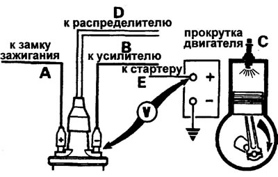
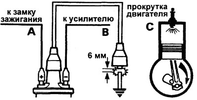
Remove the central high-voltage wire (from the ignition coil) from the distributor cap. Holding the wire tip approximately 6 mm from the cylinder block (use insulated pliers). Turn the engine over with the starter. If there is a regular spark discharge, proceed to test 6. If there is no spark formation, proceed to test 2.


Test #2


Low voltage line


Low voltage line


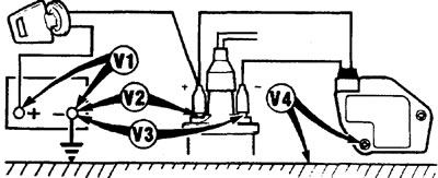
Turn on the ignition (do not start the engine).

a) Measure voltages V1 - V4 (see picture), record the voltmeter readings.

b) Compare the readings with the list below
  • V 1 is greater than 12 V
  • V2 is one volt lower than V1
  • V3 is one volt lower than V1
  • V 4 0 - 0.1 V

c) If everything is normal, then proceed to test 3.

d) Determine the fault according to the table in the "fault assumption" column.

d) If the ignition coil or amplifier may be faulty, disconnect the low-voltage wire from the coil and repeat the V3 voltage measurement. If the readings remain incorrect, replace the coil. If the voltage is normal, check the low-voltage wire and, if it is normal, replace the amplifier.

e) If the engine does not start, proceed to test 3.

1234assumption of a malfunction
N---the battery is dead
-NN-ignition switch and/or wiring
--N-ignition coil or amplifier
---INamplifier grounding

[The original article can be found here: www.LRman.ru]

  • H - low voltage
  • B - high voltage

Test #3


Amplifier


Amplifier


Connect a voltmeter to the battery "+" and the low voltage terminal of the ignition coil. The voltage should be zero.


Turn on the ignition: the voltage should be zero.

Turn the engine over with the starter. Voltage should appear: if yes, go to test 5, if not, go to test 4.

Test #4


Checking the sensor winding


Checking the sensor winding


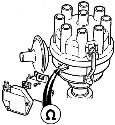
Remove the amplifier.

Measure the resistance of the distributor sensor winding. Normally, the resistance should be 2-5 kOhm. If the resistance is normal, replace the amplifier.

If the engine still does not start, proceed to test 5. After replacing the distributor sensor, proceed to test 5.

Test #5


Ignition coil


Ignition coil


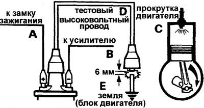
Remove the central high-voltage wire between the coil and the distributor. Install a high voltage test lead onto the coil. Holding the wire with insulated pliers 6 mm from the engine block, crank the engine with the starter. If there is no spark or the charging power is low, replace the coil and repeat the test. If spark formation is normal, repeat the test with the original wire. If there is sparking, proceed to test 6; if not, replace the high-voltage wire. If the engine does not start after replacement, proceed to test 6.


Test #6


Distributor rotor


Distributor rotor


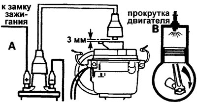
Remove the distributor cap. Remove the high voltage wire from the cover. Hold the wire tip 3 mm above the rotor electrode and crank the engine with the starter.

If a spark jumps between the rotor and the wire, proceed to test 7; if there is no spark, replace the rotor. If the engine does not start after replacement, proceed to test 7.

Test #7


Visual inspection


1. The distributor cap is clean, dry, without cracks or signs of breakdown.

2. The sensor core is clean, dry, and free of any signs of breakdown.

3. Insulation of high-voltage wires - no cracks or abrasions.

4. Conductivity of high-voltage wires - must be.

5. Spark plugs are clean, dry, with the gap between the electrons adjusted.


This article is available at russian, bulgarian, belarusian, ukrainian, serbian, croatian, romanian, polish, slovak, hungarian
Article review: Konstantin Nazarov


Previous articles
Electrical equipment — description
Generator — Description
Anti-theft system
Description of the anti-theft system (model 96)
Operation of the anti-theft system (model 96)
Checking the anti-theft system (model 96)
Checking the generator

Current article
Lucas Constant Energy Ignition System (V8i engine)

Next articles
Adjustment (ignition timing)
Fuse box (in the passenger compartment)
Fuse box (in the engine compartment)
Battery — removal and installation
Electronic ignition of the V8i engine
Ignition coil
Distributor (V8i engine)
Starter (MPi engine)


Similar articles from Land Rover repair manuals:
• Engine Ignition System Specifications Freelander 2 (2006-2014)
• Fuel system of the gasoline engine K1.8 Freelander 1 (1997-2006)
• Engine power supply system Range Rover 3 (2001-2012)
• Code Engine Control Module (PCM) malfunctions Defender 2007+ (2007-2016)

Comments on this article


No comments yet


How much will 49 + 15 =


Discovery 3 
  • General information
  • Using the manual
  • Precautionary measures
  • Service Information
  • Technique
  • Health protection
  • Road test
  • Identification codes
  • Jacking and lifting
  • Maintenance - diesel
  • Maintenance - petrol
  • Chassis
  • Suspension
  • Front suspension
  • Rear suspension
  • Wheels and tires
  • Dynamic suspension
  • Cardan shaft
  • Rear drive axle
  • Front drive axle
  • Front axle axles
  • Rear axle axles
  • Brake system
  • Parking brake
  • Hydraulic brake
  • Vacuum brake booster
  • Anti-lock braking system
  • Steering
  • Steering column
  • Power unit
  • Petrol engine 4.0L
  • Petrol engine 4.4L
  • Diesel engine 2.7L
  • Engine cooling
  • Fuel supply
  • Drive units
  • Launch system
  • Ignition system
  • Emission reduction
  • Air filtration
  • Fuel vapor control
  • Electronic control part
  • Car gearbox
  • Clutch
  • All-wheel drive systems
  • Transfer case
  • Exhaust system
  • Fuel tank and lines
  • Acceleration control
  • Electrical equipment
  • Climate control
  • Instruments and control lamps
  • Battery and charging system
  • Information system
  • Lighting and headlights
  • Power distribution
  • Electronic Function Group
  • Body and coating
  • Body elements
  • Interior and body trim
  • Mirrors and glasses
  • Seats
  • Instrument panel and console
  • Handles and locks
  • Windshield wipers and washers
  • Sunroof and bumpers
  • Safety system
  • Body repairs
  • Repair of front end elements
  • Repair of back elements
  • Side panel repair
  • Frame and body mount

Discovery 1 
  • General information
  • Technical specifications
  • Introduction to manual
  • Troubleshooting
  • Power unit
  • Diesel engine Tdi
  • Petrol engine V8i (3.9 l)
  • Petrol engine V8i (4.0 l)
  • Petrol engine Mpi
  • Reducing harmful emissions
  • Fuel system Tdi
  • Fuel system MFi
  • Fuel system SFi
  • Fuel system MPi (MEMS)
  • Cruise control
  • Cooling system (Tdi)
  • Cooling system (V8i)
  • Cooling system (MPi)
  • Exhaust system
  • Transmission
  • Clutch
  • Manual gearbox R380
  • Manual gearbox LT 77
  • Transfer case LT230T
  • Automatic gearbox
  • Cardan shaft
  • Rear axle
  • Front axle
  • Chassis
  • Steering system
  • Front suspension
  • Rear suspension
  • Brake system
  • Wheels and tires
  • Body and interior
  • Passive safety
  • Doors, locks and windows
  • Exterior body parts
  • Interior trim details
  • Seats
  • Electrical equipment
  • Heating and ventilation
  • Air conditioning
  • Windscreen wipers
  • Starting and charging system
  • Equipment and devices
  • Lighting and headlights


LRman.ru © 2013-2026 | Mobile version | Free Lander | Discovery | Range Rover | Defender | Contacts | | Sitemap |
Car repair and service instructions Land Rover: Freelander, Discovery, Range Rover, Defender
We use cookies to make pages load faster and provide a more user-friendly experience 🍪