Contents: Removal ⇩ Installation ⇩
Removal
1. Apply the parking brake.
2. Relieve any residual pressure in the fuel system (see "Fuel system").
3. Remove the hood (see "Body").
4. Remove the battery.
5. Remove the cooling system radiator.
6. Disconnect the fuel return line from the fuel manifold and plug the open ends.
7. Loosen the fuel supply line clamp.
8. Remove the vacuum hose from the fuel pressure regulator.
9. Manual transmission: disconnect the accelerator cable.
10. Automatic transmission: disconnect the throttle cable from the resonance chamber, move the bracket together with the cable to the side.
Caution: Do not change the kickdown cable adjustments.
11. Remove the Venturi nozzle housing (see "Fuel system").
12. Remove the air flow sensor.
13. Remove the air filter (see "Fuel system").
14. Remove the generator.
15. Without disconnecting the hoses, remove the air conditioning compressor from its supports and secure it to the side.
Note: Remove the air conditioner mounting bracket and install the ETC 5964 engine lift bracket in its place.
16. Place a container under the engine to collect the fluid.
17. Disconnect the power steering pump hoses. Secure the hoses above the fluid level in the pump reservoir to prevent excessive fluid loss.
18. Disconnect the power steering pump from its housing. Cap hoses and fittings to prevent dirt from entering. Wipe up any spilled liquid.
19. Disconnect the fuel and coolant temperature sensor connectors.
20. Disconnect the wires from the ignition coil.
21. Mark the injector connectors and disconnect the connectors.
22. Disconnect the wiring harness from the fuel rail, move it to the side and secure it.
23. Disconnect the two transmission cooler tube support brackets from the block.
24. Remove the engine mount fasteners from both sides of the engine.
25. Attach the sling to the engine lifting hooks. Sizes of the branches of the chalka (see picture):
- (1) left anterior branch - 356 mm
- (2) right anterior branch - 330 mm
- (3) right posterior branch - 457 mm
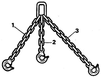
Note: The length of the sling branch is measured from the eye of the hook to the last link of the chain.
26. Secure the sling to the lift, lift the engine so that the engine mount cushions can be removed, and remove the cushions.
27. Lower the engine until it rests on the support brackets. Take off the bangs.
28. Disconnect the two heater hoses from the right valve cover.
29. Disconnect the ground wire from the left head. Do not remove the wire from the clip.
30. Disconnect all wires from the clips at the rear of the engine.
31. Remove the gearbox ventilation tubes from the rear engine lifting hook.
32. Remove the two inner clutch housing mounting bolts (torque converter).
33. Raise the front of the car and place struts under the front axle pipes.
34. Remove the lower clutch housing cover and its gasket.
35. Unscrew the nuts securing the exhaust system inlet pipes from the exhaust manifolds. Remove the heat shield from the right pipe.
36. Disconnect the wires from the starter. If a fuel level sensor is installed (on a pallet) - disconnect its connector.
Note: items 36, 37, 38, 39 are only for automatic transmission.
37. Rotate the crankshaft until the automatic transmission drive clutch mounting bolts appear in the two windows of the torque converter housing.
38. Unscrew the two bolts and mark the relative positions of the drive halves in one place.
39. Turn the crankshaft 180 degrees and unscrew the remaining two half coupling bolts.
40. Unscrew the remaining clutch housing mounting bolts (torque converter).
41. Disconnect the starter ground wire from the frame.
42. Place the car with its wheels on the ground.
43. Place a temporary support under the checkpoint (for example, a jack).
44. Secure the sling. Raise the engine until it is disconnected from the gearbox.
45. Check that all wires and tubes are disconnected.
46. Slowly remove the engine from the engine compartment and place it on supports.
Installation
47. Raise the engine on a lift.
48. Start the engine in the engine compartment.
49. Automatic transmission: turn the crankshaft until the holes for the drive coupling bolts are aligned with the windows in the crankcase. Check the presence of crankcase guide pins in the block.
Manual transmission: Lower the engine and engage the input shaft of the transmission. Install the clutch housing onto the guide pins.
50. Lightly tighten the clutch housing mounting bolts (torque converter).
51. Lower the engine onto the supports, remove the temporary gearbox support.
52. Install the two upper clutch housing mounting bolts and tighten them to 40 Nm.
53. Install the remaining bolts and tighten them to 40 Nm.
54. Automatic transmission: align the previously made marks of the relative position of the drive half couplings, tighten the two mounting bolts to a torque of 40 N·m.
55. Turn the crankshaft 180 degrees and tighten the remaining two bolts to 40 Nm.
56. Install the lower clutch housing cover with a new gasket, tighten the mounting bolts to a torque of 9 N·m.
57. Install new exhaust manifold gaskets and secure the exhaust system inlet pipes.
58. Secure all removed parts to the rear of the engine.
59. Raise the engine and install the engine mounts. Tighten the mounting bolts to 20 Nm.
60. Remove the temporary lifting hook ETC 5964.
61. Install the removed parts (item 23-1).
Comments on this article