Contents: Removal ⇩ Installation ⇩
Removal
CAUTION: Wait at least 30 seconds after stopping the engine before attempting any repairs to the high pressure fuel injection system. Failure to follow this instruction may result in personal injury.
CAUTION: Do not carry or use a cell phone when working with any fuel-related parts or in the immediate vicinity of such parts. There is a risk of ignition of highly flammable vapors. Failure to follow these instructions may result in personal injury.
WARNING: Do not smoke or carry a lighted cigarette or open flame of any type when working on or near fuel-related components. There is a risk of ignition of flammable vapors. Failure to follow these instructions may result in personal injury.
CAUTION: This procedure involves handling fuel. Always be prepared for possible fuel splashing and follow fuel handling precautions. Failure to follow these instructions could result in injury.
CAUTION: Do not carry out any repairs to the fuel injection system while the engine is running. Fuel pressure in the system can reach 1650 bar (23,931 psi). Failure to follow this instruction may result in injury.
CAUTION: Make sure that the area of the workshop where the vehicle is being worked on is as clean and dust-free as possible. Dirt and dust from clutch, brake, machining or welding operations can contaminate the fuel system and cause malfunctions.
CAUTION: Always perform the cleaning procedure before performing any repairs to fuel injection system components. Failure to follow this instruction may result in dirt entering the fuel injection system.
CAUTION: Diesel fuel injection equipment is manufactured to very precise tolerances and with very small clearances. It is therefore especially important to maintain absolute cleanliness when working on these components. Open holes or lines should always be plugged using suitable plugs. Failure to follow this instruction may result in dirt entering the fuel injection system.
1. Disconnect the ground cable from the battery. For more information, refer to Specification.
2. Remove the air intake throttle valve. For more information, refer to Air Intake Valve (19.70.32)
3. Remove the accessory drive belt. For more information, refer to Accessory Drive Belt (86.10.03)
4. Remove the auxiliary drive belt idler pulley. Remove the bolt.
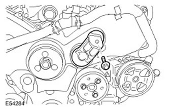
5. Disconnect the knock sensor wiring harness from the cylinder head cover.
6. Disconnect the knock sensor electrical connector.
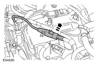
7. Disconnect the glow plug wire harness from the cylinder head cover.
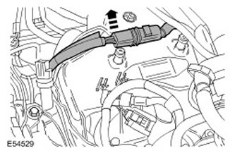
8. Disconnect the engine oil pressure (EOP) sensor electrical connector.
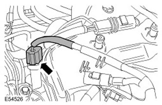
9. Disconnect the breather from the cylinder head cover.
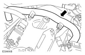
10. Remove the fuel injector. For more information, refer to Fuel Injector (19.60.10)
11. Remove the 2 remaining fuel injectors.
12. Loosen the high pressure fuel supply line fastening. Unscrew the bolt.
13.
CAUTION: Make sure that the high pressure fuel supply line remains in contact with the fuel pump and fuel rail until both connections have been disconnected and cleaned. Failure to follow this instruction may result in dirt entering the fuel injection system.
Remove and discard the high pressure fuel supply line. Plug any exposed connections.
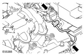
14. Remove the fuel manifold. Remove the two remaining bolts.
The original article can be found here www.lrman.ru
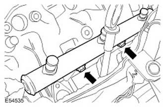
15. Remove the fuel rail support bracket.
- Loosen the dipstick tube mount.
- Remove the three remaining bolts.
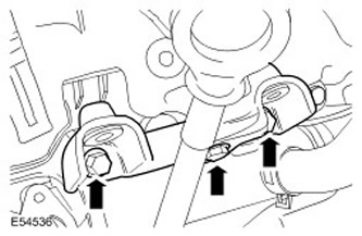
16. Remove the engine cover guide pins.
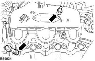
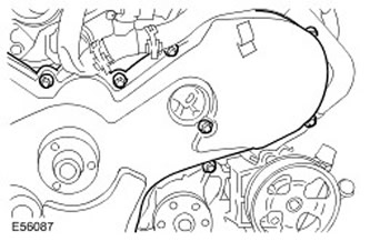
17. Loosen the timing belt cover fastening.
- Replace the timing belt cover to gain access to the two front cylinder head cover bolts.
- Completely loosen the seven indicated timing belt cover screws.
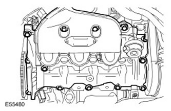
18. Remove the left cylinder head cover. Loosen the 13 cylinder head cover fastening screws.
Installation
1. Install the left cylinder head cover. Tighten the 13 screws. (tightening torque 10 Nm).
2. Install the timing belt cover. Tighten the 7 screws. (tightening torque 10 Nm).
3. Install the engine cover guide pins.
4. Install the high pressure fuel supply line support bracket.
- Install two bolts.
- Tighten the bolts (tightening torque 23 Nm).
- Secure the dipstick tube.
6. Install the new high pressure fuel supply line.
- Open the holes covered with plugs.
- Install the new high pressure fuel supply line, but do not tighten the connections yet.
- Tighten the fuel rail support bracket mounting screws. (tightening torque 23 Nm).
- Tightening of the connections of the new high-pressure fuel supply line is carried out in four stages in the specified sequence:
- Step 1: Tighten the high pressure fuel supply line connection to the manifold. (tightening torque 15 Nm).
- Step 2: Tighten the high pressure fuel supply line connection to the fuel rail (tightening torque 15 Nm).
- Step 3: Tighten the high pressure fuel supply line connection to the manifold. (tightening torque 30 Nm).
- Step 4: Tighten the high pressure fuel supply line connection to the fuel rail (tightening torque 30 Nm).
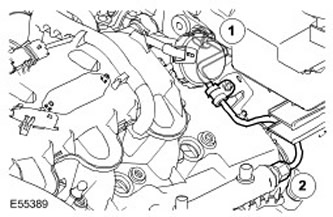
7. Secure the high pressure fuel supply line. Tighten the remaining bolt. (tightening torque 10 Nm).
8. Install the fuel injector. For more information, refer to Fuel Injector (19.60.10)
9. Install the remaining 2 fuel injectors.
10. Attach the breather to the cylinder head cover.
11. Connect the engine oil pressure (EOP) sensor electrical connector.
12. Connect the knock sensor electrical connector.
13. Connect the glow plug wire harness to the cylinder head cover.
14. Install the accessory drive belt pulley. Insert the bolt and tighten it. (tightening torque 47 Nm).
15. Install the accessory drive belt. For more information, refer to Accessory Drive Belt (86.10.03)
16. Install the air intake throttle valve. For more information, refer to Air Intake Damper (19.70.32)
17. Connect the ground cable to the battery. For more information, refer to Specification.
Comments on this article