Contents: Removal ⇩ Removal the throttle lever ⇩ Checking and repairing the throttle…⇩ Checking and repairing the throttle…⇩ Assembling the throttle lever ⇩ Installation ⇩
Removal
1. Disconnect the battery.
2. Disconnect the idle air control valve connector.
3. Disconnect the vacuum hose located next to the valve.
4. Mark the position of the accelerator cable adjusting nuts to facilitate subsequent installation.
5. Remove the cotter pin securing the cable eye.
6. Remove the accelerator cable from the bracket and place it aside.
7. Remove the kick-down cable stopper and remove the cable eye pin (only for automatic transmission).
8. Wrap electrical tape around the kickdown cable near the adjustment unit to secure the adjustment nut.
9. Loosen the lock nut of the adjustment unit, remove the cable from the bracket and move it to the side.
10. Disconnect the cruise control system vacuum hose.
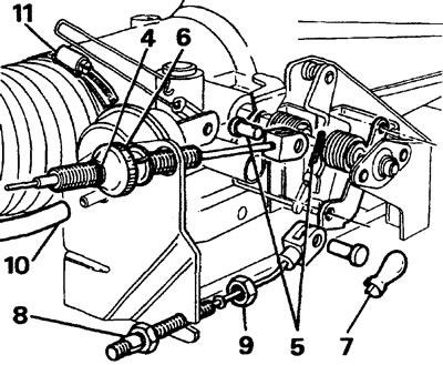
11. Remove the air hose from the neck of the resonance chamber.
12. Disconnect the throttle position sensor connector.
13. Remove the crankcase ventilation hose.
14. Disconnect and plug the two cooling system hoses. Mark the hose connection locations.
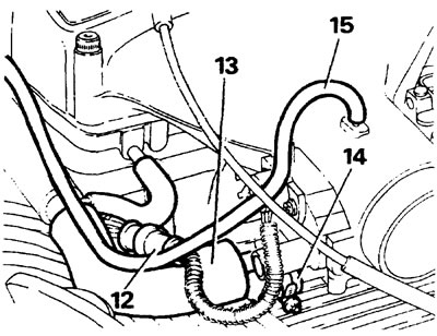
15. Remove the distributor vacuum hose.
16. Loosen the two screws securing the throttle position sensor and remove the sensor.
17. Unscrew the six bolts securing the resonance chamber and remove the resonance chamber.
18. Disconnect the idle air control valve hose.
Removal the throttle lever
19. If installed, disconnect the cruise control drive rod, fully open the throttle valve, disconnect the rod from the intermediate shaft. Carefully return the throttle to the closed position.
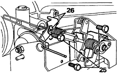
20. Release the tension of the inner throttle spring.
21. Bend back the tabs of the lock washer.
22. Holding the throttle at the closed position stop, unscrew the throttle shaft nut.
23. Relieve tension on the outer throttle spring.
24. Remove the compensation spring.
25. Unscrew the three bolts securing the throttle bracket to the resonance chamber and remove the bracket.
26. Remove the lock washer and throttle stop lever from the throttle shaft.
Checking and repairing the throttle lever
27. Remove the two spherical bushing retaining rings.
28. Remove the intermediate shaft.
29. If the spherical bushing is worn, drill out the rivets with a 04.7 mm drill.
30. Disassemble the unit and discard the worn bushing.
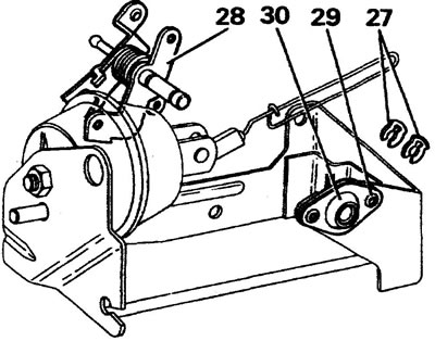
31. Lubricate the new bushing with Admax L3 or Energrease LS3 grease. Install the bushing into the housing. Secure the bushing with two 04.7mm rivets.
32. Check the bearing seats of the intermediate shaft. If there is wear, install a new unit by repositioning the lever springs.
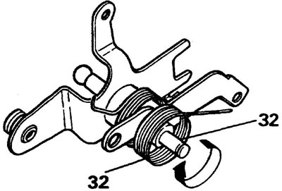
33. First hook the spring.
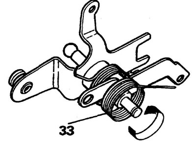
34. Lubricate the shaft with Admax L3 grease, install the shaft into the spherical bushing, secure the shaft with two retaining rings.
35. Check the throttle lock lever for wear. Replace if necessary.
Checking and repairing the throttle valve
36. Check for wear between the throttle shaft and the resonance chamber bushings; only a small gap is allowed, otherwise replace the shaft and bushings, see below.
37. Unscrew the two screws securing the throttle valve to the shaft and remove the valve.
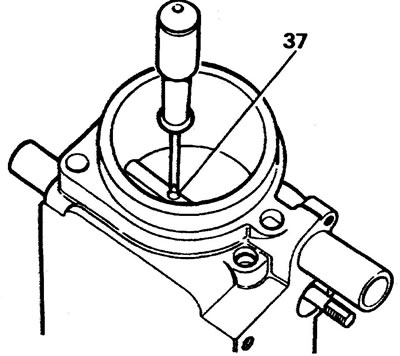
38. Remove the shaft and seals from the resonance chamber.
The article is based on data from the website LRMAN.ru
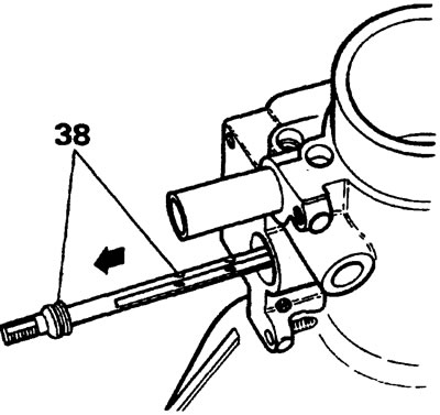
39. Using a suitable drift, knock out the resonance chamber bushings. Caution! Do not damage the resonance chamber housing.
40. Press in new bushings.
Note: The bushing must not extend beyond the surface of the valve opening.
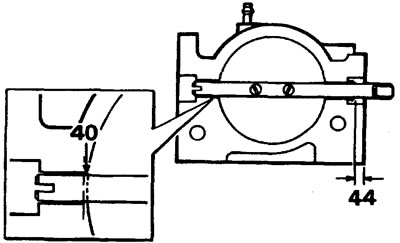
41. Install the throttle valve on the shaft and tighten it (not completely!) two split screws.
42. Rotate the damper 360° two or three times to center the damper, tighten the screws.
43. Spread the slots of the mounting screws.
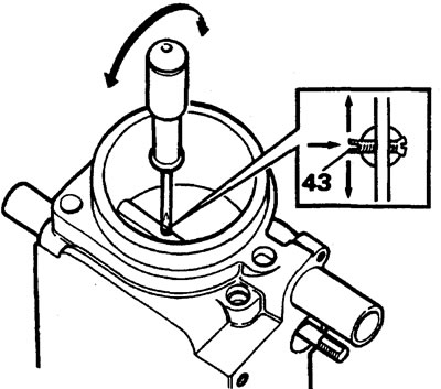
44. Lubricate the shaft seal with Admax L3 grease, insert the seal into the housing to a depth of 6 mm.
Assembling the throttle lever
45. Place the limiter lever on the shaft, install a new lock washer and tighten the nut by hand.
46. While holding the throttle in the closed position, finally tighten the fastening nut, bend the tab of the lock washer onto the edge of the nut.
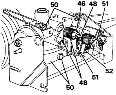
47. Install the inner return spring with the small hook towards the resonance chamber.
48. Place the spring hook behind the lever. Turn the straight end of the spring one turn and insert it into the corresponding slot.
49. Install the intermediate shaft into the throttle shaft sleeve.
50. Secure the lever bracket with three bolts.
51. Attach the outer spring hook to the lever, turn the straight end one revolution and insert it into the corresponding slot.
52. Secure the compensation spring. Lightly lubricate the springs with Admax L3 or Evergrease LS3.
Note: When installing a new throttle body, ensure that the body fits snugly against the throttle body at an arc of at least 90° around the circumference.
53. Measure the distances between the upper and lower edges of the throttle valve and the edge of the resonance chamber. The difference in distances should be 0.5 mm.
54. If the difference in distances is not equal to the specified value, adjust the position of the damper by turning the limiting lever screw.
Installation
55. Connect and adjust the cruise control linkage, see below.
56. Clean the mating surfaces of the resonance chamber and the venturi housing. Apply Hylomar sealant and tighten the bolts to 26 Nm.
57. Reinstall the removed parts.
Comments on this article