The headlights are sealed blocks with scratch-resistant polycarbonate lenses that are glued to the headlight housing. Two sealed access covers and a sealed housing provide a waterproof environment for the internal headlight components. To prevent fogging of the lens and allow the headlamp to 'breathe' in response to changes in internal temperature, a ventilation hole is provided on the outer rear surface of the headlight housing. The vent is covered with a Gortex waterproof membrane. This allows the headlight to ventilate while preventing water from entering.
The headlights can be quickly removed for bulb replacement thanks to the unique 'Rail Lock' system. Access to the headlight requires unscrewing the two bolts securing the headlight to the hood closing panel. The locking lever at the rear can then be raised by releasing the locking element at the base of the headlight housing. You can then pull the headlight forward along the guide and, after disconnecting the wiring harness connector, remove it from the vehicle. The 'Rail Lock' system ensures that the headlight adjustment is not lost when it is removed.
Each headlight has two technology covers at the back. The large cover requires the locking lever to be released from its guide slots in order to gain access to it. The cover can then be removed by releasing the two tabs to replace the high and low beam bulbs. The round rubber cover is a snug fit on the back of the headlight assembly. Removing the cover gives access to the parking light and turn signal lamps.
On NAS vehicles, the position light has an orange lens. The side light lens is designed so that the light from the side light lamp also illuminates the orange reflector area on the side of the light without the need for an additional lamp.
Halogen headlights
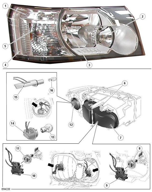
| Pos. | spare part no | Name |
| 1 | - | marker light (and side marker light on NAS vehicles) |
| 2 | - | Halogen high beam |
| 3 | - | Halogen low beam |
| 4 | - | Side marker reflector (NAS vehicles only) |
| 5 | - | Direction indicator lamp |
| 6 | - | Manual headlight dimmers |
| 7 | - | Lid |
| 8 | - | High beam halogen lamp |
| 9 | - | high beam bulb holder |
| 10 | - | low beam bulb holder |
| 11 | - | Halogen low beam |
| 12 | - | Lid |
| 13 | - | Turn signal lamp |
| 14 | - | turn signal bulb socket |
| 15 | - | marker lamp holder |
| 16 | - | marker lamp |
The halogen headlight for other countries has two H7 55W halogen bulbs for high beam and low beam. On NAS vehicles, the low beam halogen headlight uses an H11 55W halogen bulb.
Bi-xenon headlights
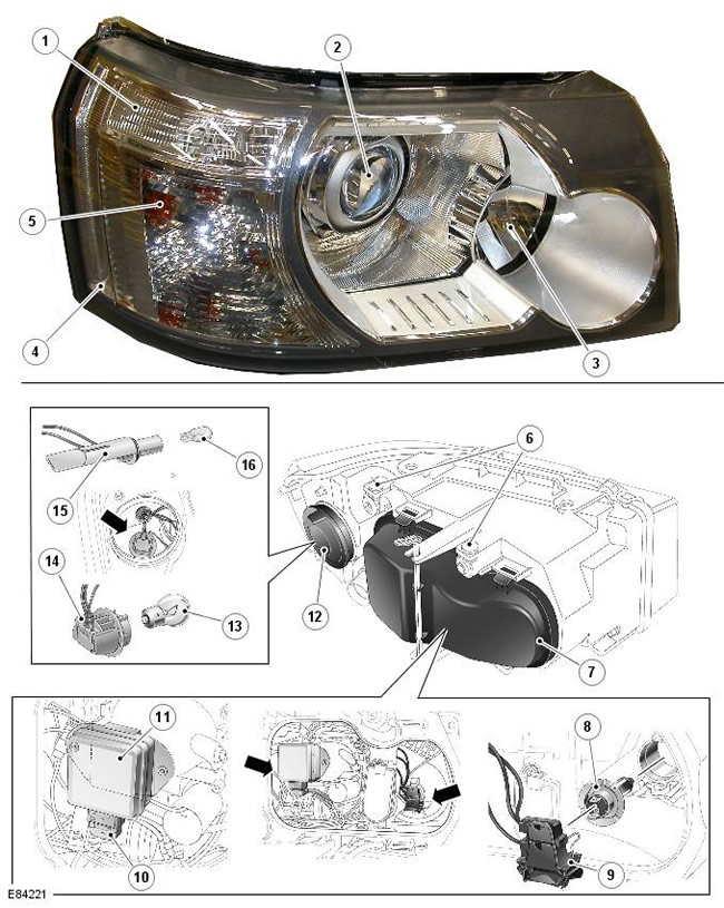
| Pos. | spare part no | Name |
| 1 | - | marker light (and side marker light on NAS vehicles) |
| 2 | - | Bi-xenon low and high beam headlight |
| 3 | - | Halogen high beam |
| 4 | - | Side marker reflector (NAS vehicles only) |
| 5 | - | Direction indicator lamp |
| 6 | - | Manual headlight dimmers |
| 7 | - | Lid |
| 8 | - | High beam halogen lamp |
| 9 | - | high beam bulb holder |
| 10 | - | D1S bi-xenon bulb electrical connector |
| 11 | - | Bi-xenon lamp D1S |
| 12 | - | Lid |
| 13 | - | Turn signal lamp |
| 14 | - | turn signal bulb socket |
| 15 | - | marker lamp holder |
| 16 | - | marker lamp |
The xenon headlight uses a complex surface reflector for the high beam halogen lamp only. Uses the same H7 55W halogen bulb as the halogen headlight. A bi-xenon module is installed for the low beam headlight, but it also works as a high beam.
Precautionary measures
The following precautions must be observed when working on the xenon headlight system:
- It is FORBIDDEN to carry out any work on xenon headlights when the lights are on.
- D1S xenon lamps must only be handled with personal protective equipment such as gloves and goggles.
- Do not touch the glass bulb of the lamp.
- Disposal of xenon lamps must be carried out according to the rules for the disposal of hazardous waste.
- You can turn on the lamp only when it is in the installed position, in the reflector.
WARNING: Xenon lamp supply voltage reaches 28000 V. Contact with such voltage can be fatal. Before carrying out work on the headlights, they must be turned off.
The design and functionality of the headlight
As part of a xenon or gas-discharge (HID) headlights includes a curtain controlled by an electromagnet, changing the beam of the high beam to the beam of the dipped beam and vice versa.
NOTE: If the light control module rotary switch is in the off position, xenon high beam signaling is not possible. If the rotary switch is in the headlights on position or in the AUTO position and the dipped beam headlights are on, the xenon dipped beam remains on when the xenon headlights are signaling high beams.
The operation of the xenon headlights is controlled by the CJB, which is connected to the control modules of each of the headlights and to the discharge starter. Control modules and starters provide xenon lamps with enough electricity to turn them on.
The xenon headlight is an independent structural element, which is located in the headlight assembly. The main elements of a xenon headlight are a reflector, a diffuser, a curtain controller and a xenon lamp.
The reflector provides support for the xenon lamp, which is an integral part of the lamp starter. The starter is located in the opening at the rear of the reflector and secured with two Torx screws to ensure proper alignment in the reflector.
The shutter is used to switch from low beam to high beam and vice versa. The shutter drive is an electromagnet that controls the position of the shutter using a lever mechanism. When the blind is in the low beam position, it covers part of the light emitted from the reflector, providing a certain low beam cutoff.
The linkage is on the right side of the headlight. This mechanism operates a curtain that blocks part of the light beam, which allows you to drive the car along «wrong» side of the road without the use of special stickers on the headlight lens. The beam of light is changed by moving the cover at the back of the headlight and moving the small lever that is located on the side of the headlight.
A xenon lamp is lit when an electric current is passed between two electrodes inside the lamp and an electric arc is formed. The hermetic bulb of the lamp contains xenon gas, which, under the influence of an electric discharge and heating, goes into an excited state and emits light in the blue-white part of the spectrum.
The output to the maximum level of continuous illumination of the lamp is carried out in three phases. These are the ignition phase, the warm-up phase and the continuous operation phase.
In order for an electric arc to form, an initial voltage of up to 30,000 V must be applied to the lamp during the ignition phase. This voltage is provided by xenon lamp starters. After the formation of an electric arc, the warm-up phase begins. Xenon headlight control modules regulate the electric current in the lamp circuits so that the current is 2.6 A, which corresponds to a power of 75 watts. During this phase, a bright glow of xenon begins, and the lamp goes into a steady state of operation with stable parameters for the flow of electric current between the electrodes. Once the warm-up is over, the control module enters the steady state phase. The voltage applied to the lamp electrodes is reduced, and the power to maintain the steady state is reduced to 35 watts. The transition from the ignition phase to the steady state phase takes a very short time.
The xenon headlights are controlled by the CJB unit, two headlight control modules and two starters. When the headlights are turned on, the CJB module supplies electrical voltage to the control modules (one for each headlight). During the ignition phase, the control modules regulate the voltage level at the lamp electrodes.
Starters (one for each headlight) create a high initial voltage, which is necessary for the formation of an electric arc between the electrodes. The starters are designed with coils that generate the high voltage pulses needed to start the lamp. As soon as the lamp starts to work, the starter forms a closed control loop, allowing the control module to regulate the supply voltage.
Comments on this article