Contents: Removal ⇩ Installation ⇩
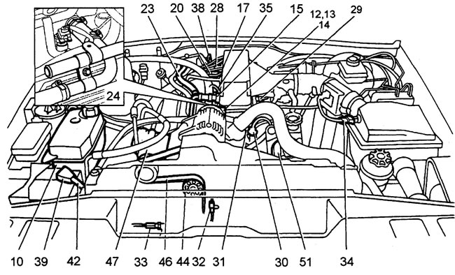
Removal
1. Place the car on a lift.
2. Remove the hood (see "Body").
3. Remove the radiator (see section "Cooling system").
4. Remove the resonance chamber (see "Fuel system").
5. Remove the air flow sensor (see "Fuel system").
6. Loosen the clamp of the lower hose of the expansion tank.
7. Disconnect the hose.
8. Unscrew the two nuts securing the expansion tank.
9. Unscrew the nut and bolt securing the expansion tank.
10. Remove the expansion tank.
11. Disconnect the brake booster hose.
12. Disconnect the battery cable from the generator (Lucar).
13. Remove the generator terminal cover.
14. Disconnect the two wires from the generator.
15. Remove the drain hose from the brake booster housing.
16. Place a rag around the fuel line connector to collect the fuel.
17. Loosen the fuel return line clamp on the fuel manifold.
18. Disconnect the fuel line.
19. Plug the fuel line and the fuel manifold fitting.
20. Loosen the fuel supply line mounting bolt and disconnect the fuel line.
21. Plug the fuel line and fitting.
22. Loosen the heater hose clamp.
23. Disconnect the hose.
24. Loosen the heater adapter hose clamp on the intake manifold.
25. Loosen the bolt of the tube support bracket.
26. Disconnect the adapter hose from the intake manifold.
27. Disconnect the heater hoses and pipes.
28. Disconnect the high-voltage wires from the spark plugs and remove the ignition coils (see "SFI fuel system").
29. Disconnect the fuel temperature sensor connector.
30. Disconnect the coolant temperature sensor connector (control systems).
31. Disconnect the coolant temperature sensor connector (temperature indicator).
32. Release the camshaft position sensor connector from the clip and disconnect the connector.
33. Disconnect the oil pressure sensor connector.
34. Disconnect the air temperature sensor connector.
35. Disconnect the eight injector connectors.
36. Remove the four nuts from the wiring support bracket.
37. Remove the wiring bracket.
38. Disconnect the gearbox ventilation tube from the engine lifting hook.
39. Remove the positive battery terminal cover.
40. Unscrew the terminal nut.
41. Remove the wires from the battery.
42. Disconnect the main wire from the fuse box.
43. Place the wires on the engine.
44. Tilt the belt tensioner roller downwards to release the belt tension.
45. Remove the accessory belt from the pulleys.
46. Put the belt aside.
47. Disconnect the air conditioning compressor connector.
48. Unscrew the four compressor mounting bolts.
49. Remove the heat shield.
50. Remove the compressor and hang it aside.
51. Release the power steering pump hose from the clip.
52. Disconnect the hose.
53. Plug the hose and pump nipple.
54. Disconnect the hose from the pump and the power steering actuator.
55. Unscrew the hose mounting bolts and remove the hose.
56. Remove and discard the hose bolt sealing rings.
57. Plug the pump and power steering nipples.
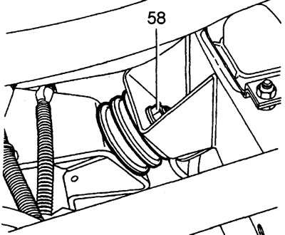
58. Unscrew the nuts of the left and right engine mounts.
59. Attach the sling to the engine lifting hooks.
60. Raise the engine until its mounts are free.
61. Remove the engine mount cushions.
62. Lower the engine to its original position.
63. Remove the sling.
64. Raise the car on a lift.
65. Remove the exhaust pipe.
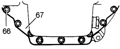
66. Remove the 9 transmission housing cover mounting bolts. Note the location of the two guide bolts.
67. Remove the cover.
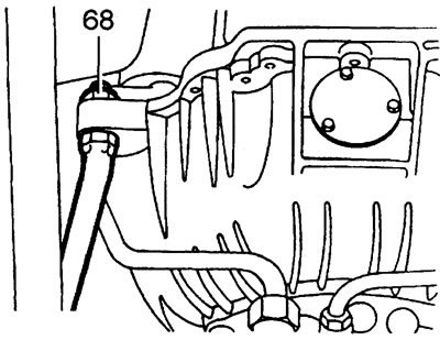
68. Loosen the lock nut of the transfer case torque rod.
69. Unscrew the 2 bolts securing the torque rod to the gearbox.
70. Remove the thrust rod.
71. Unscrew two and loosen one bolt of the access hole cover in the automatic transmission housing.
72. Apply marks to the relative positions of the automatic transmission drive coupling halves.
73. Rotate the crankshaft until the half coupling mounting bolt is aligned with the access hole.
74. Remove the first bolt.
75. Repeat step 73 to remove the remaining three bolts.
76. Loosen the two crankshaft position sensor mounting bolts (see "SFI fuel system").
77. Remove the sensor from the engine.
78. Disconnect the sensor connector.
79. Put the sensor aside.
80. Remove the starter heat shield.
81. Disconnect the starter solenoid wire.
82. Disconnect the connectors of the right and left knock sensors.
83. Disconnect the wiring connector from the engine.
84. Remove the parking brake cable heat shield.
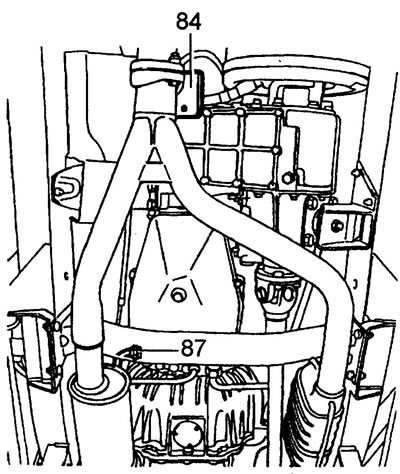
85. Release the vehicle speed sensor wire from the heat shield clip.
86. Remove the heat shield.
87. At the gearbox, loosen the upper oil cooling pipe bolt.
88. Unscrew the tube bolt.
89. Remove the rubber seal from the bolt and discard.
90. Plug the pipe and the gearbox fitting.
91. Unscrew the bolt securing the cooler bracket to the pan, do not lose the spacer.
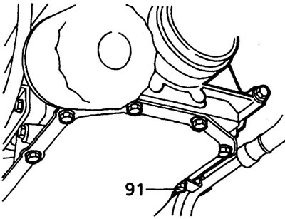
92. Unscrew the three upper bolts of the gearbox housing.
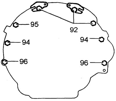
93. Set aside the two wiring support brackets.
94. Unscrew two (left and right) middle bolts of the gearbox housing.
95. Using a long extension, remove the central crankcase bolt.
96. Unscrew the two lower bolts of the gearbox housing.
97. Place a suitable block of wood into the access hole to prevent the torque converter from falling out.
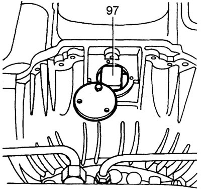
98. Secure the block with the hole cover and tighten the mounting bolts.
99. Place a temporary support (jack) under the gearbox.
100. Lower the lift and jack together.
101. Secure the sling to the engine.
102. Raise the engine.
103. Raise the jack.
104. Disconnect the engine from the gearbox.
105. Raise the engine.
106. Disconnect the starter ground wire.
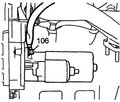
107. Disconnect the nut securing the kick-down cable clip to the left cylinder head.
108. Raise the engine, make sure nothing interferes with removal, remove the engine from the engine compartment.
Installation
109. Clean the mating surfaces of the engine and gearbox.
110. Clean the guides and the pin hole.
111. Carefully lower the engine into the engine compartment.
112. Install the kickdown cable clip onto the left head.
113. Secure the clip with a nut.
114. Secure the ground wire to the starter. Tighten the bolt to 45 Nm.
115. Lower the engine lower.
116. Align the engine with the gearbox.
117. Tighten the three lower gearbox housing bolts to a torque of 45 Nm.
118. Lower the gearbox support jack.
119. Lower the engine onto the support brackets.
120. Tighten the right middle bolt of the gearbox housing.
121. Tighten the left middle bolt of the gearbox housing.
122. Install wiring support brackets under the two upper crankcase bolts.
123. Tighten the two upper bolts to 45 N·m.
124. Remove the plugs from the oil cooling pipe and the gearbox fitting.
125. Clean the tube, install a NEW O-ring and lubricate with engine oil.
126. Secure the tube to the gearbox with a torque of 30 Nm.
127. Align the holes of the tube support bracket, spacer and pan. Tighten the mounting bolt to 18 Nm.
128. Install the heat shield. Tighten the mounting nut.
129. Secure the speed sensor wire to the screen clip.
130. Loosen the gearbox housing access hole cover bolts.
131. Move the lid.
132. Remove the torque converter retaining block.
133. Align the previously made marks of the relative positions of the gearbox drive half couplings.
134. Tighten the two half coupling mounting bolts.
135. While turning the engine, install the remaining bolts. Tightening torque 45 Nm.
136. Turn the engines and tighten the first bolt.
137. Clean the mating surfaces of the gearbox housing and cover.
138. Install the cover and tighten the 9 mounting bolts to 45 Nm.
139. Replace the access hole cover.
140. Tighten the mounting bolts to 9 Nm.
141. Lay out the wiring harness on the engine.
142. Connect the knock sensor connectors.
143. Connect the starter solenoid wire.
144. Attach the heat shield to the starter.
145. Align the screen bracket hole with the hole in the engine mount, tighten the mounting bolt to 9 N·m.
146. Clean the crankshaft position sensor mating surface.
147. Install the sensor and connect its connector.
148. Tighten the sensor mounting bolts to 6 Nm.
149. Install the transfer case torque rod onto the gearbox, tighten the bolts to a torque of 25 Nm.
The original text can be found at (LRman.ru)
150. Tighten the torque rod lock nut to 45 Nm.
151. Install the catalytic converter and exhaust pipe.
152. Raise the engine.
153. Install the right support cushion.
154. Move the engine.
155. Install the left support cushion.
156. Lower the engine.
157. Remove the sling.
158. Tighten the support nuts to a torque of 45 N·m.
159. Remove the plugs from the pump and power steering nipples.
160. Clean the booster hose bolts.
161. Put on new sealing rings, lubricate with transmission oil.
162. Install the hose back in place.
163. Tighten the hose fasteners:
- M14 - torque 15 Nm
- M16 - torque 20 Nm
164. Reinstall the removed parts in the reverse order of removal.
165. Bleed the power steering system.
166. Drain the engine oil and fill with fresh oil.
167. Start the engine. Make sure there are no fluid leaks.
Comments on this article