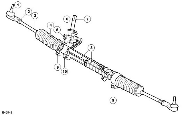
| Item name | Spare part number | Description |
| 1 | - | Tie rod end |
| 2 | - | Lock-nut |
| 3 | - | Tie Rod |
| 4 | - | Case |
| 5 | - | Connecting the inlet/outlet pipelines to the pump |
| 6 | - | Valve housing |
| 7 | - | input shaft |
| 8 | - | Inlet/outlet pipelines |
| 9 | - | Steering gear housing fixings |
| 10 | - | gear housing |
The steering gear is located in front of the engine, under the accessory drive belt. The steering gear is mounted on the chassis using two brackets to which it is attached with flange bolts and slotted nuts. A special device on the nut prevents it from turning when loosening and tightening the bolt. Castellated nuts are used only once and must be replaced after the mechanism has been dismantled. Nylock M12 nuts can be used to replace castle nuts.
The steering mechanism has a one-piece cast aluminum housing that contains a mechanical steering rack, hydraulic valve and hydraulic booster.
The steering mechanism uses a piston rod that moves in the housing on plain bearings. The drive gear connected to the hydraulic distributor rests on bearings and engages with the teeth of the rack. The gear rack is pressed against the gear by a spring-loaded plunger. This ensures the engagement of the teeth with minimal backlash. The gear is connected to the hydraulic distributor by a torsion bar. The rotational movement of the steering wheel is converted into linear movement by rack and pinion. This operation is initiated by the hydraulic valve. The movement is converted into wheel rotation by adjustable rods.
On one side of the mechanism body is a hydraulic booster piston with a diameter of 49 mm. Both ends of the piston are connected to the pressure chamber and the return chamber, which are connected to the hydraulic distributor by means of external metal tubes.
Each end of the mechanism has a threaded hole for attaching the rod. The outer ends of the mechanism are covered with covers that protect it from the penetration of dirt and moisture. The rod has a long threaded shank on which the rod end is attached. The thread allows you to adjust the convergence of the steered wheels. After setting the appropriate convergence, the position of the tips of the rods is fixed by tightening the locknuts.
A central hole runs along the entire length of the mechanism. This opening ensures the balance of air in the covers when turning the wheels. Covers can be replaced and are attached to the body of the mechanism and rods with special clamps.
Comments on this article